
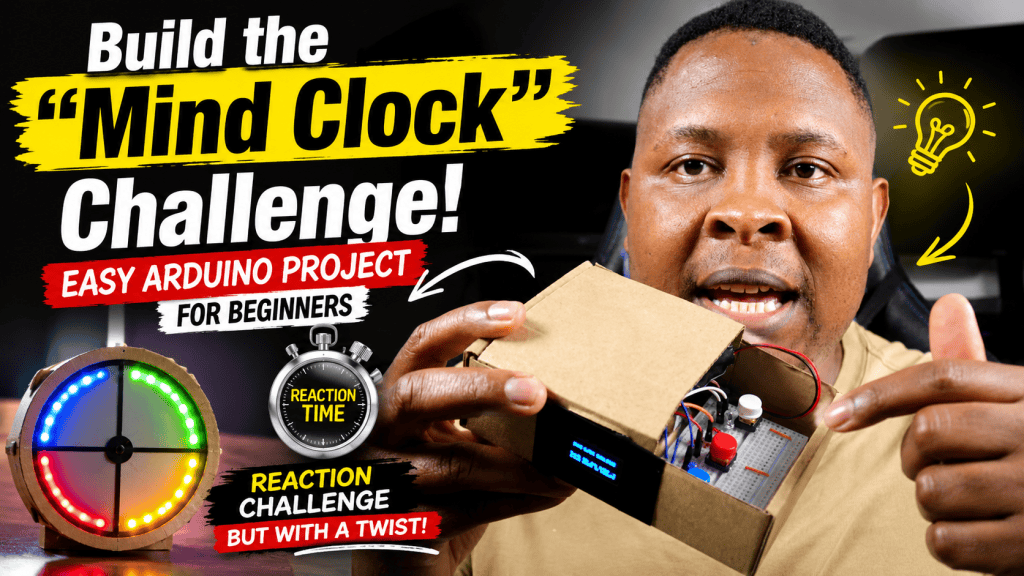
If you are looking for a project that transitions you from simply blinking an LED to building a fully interactive device, you have found it. The Mind Clock Challenge is a 2-player game where participants compete to guess exactly when a specific amount of time has passed.
This project is fantastic for beginners and STEM teachers because it combines inputs (buttons), outputs (LEDs), and visual data (an OLED screen) using a programming concept called a “state machine.”
You can also watch the video below on how to build the project:
The Hardware Connections
Here is exactly how to wire the components. Notice that we do not use resistors for the buttons! We are using a clever software trick called INPUT_PULLUP to use the Arduino’s built-in resistors instead.
How the OLED Screen Works
The 0.96″ OLED screen used in this project is incredibly powerful for its size. It uses a communication protocol called I2C (Inter-Integrated Circuit).
Instead of needing 8 or 10 wires to control the thousands of pixels on the screen, I2C only requires two data wires:
-
SDA (Serial Data): This wire carries the actual data instructions (like “turn on this pixel”).
-
SCL (Serial Clock): This wire keeps the Arduino and the screen synchronized so they understand each other perfectly.
We use the Adafruit_SSD1306 library to make controlling this screen as easy as printing text to a computer monitor.
The Code Explained
Here is the complete, heavily-commented code. There are a few core concepts at play here:
-
State Machine: The variable
gameStatetracks if we are waiting (0), playing (1), or looking at results (2). This keeps our code organized. -
millis(): Instead of using
delay()which pauses the entire Arduino, we usemillis()(the Arduino’s internal stopwatch) to track time. This allows the Arduino to keep watching for button presses while the clock runs!
C++
// Include the libraries needed to communicate with the OLED screen
#include <Wire.h>
#include <Adafruit_GFX.h>
#include <Adafruit_SSD1306.h>

// Set the resolution of our screen
#define SCREEN_WIDTH 128
#define SCREEN_HEIGHT 64

// Initialize the OLED display using the I2C protocol
Adafruit_SSD1306 display(SCREEN_WIDTH, SCREEN_HEIGHT, &Wire, -1);

// Define exactly which pins our hardware is connected to
const int btnStart = 3;
const int btnPlayerA = 2;
const int btnPlayerB = 4;
const int ledA = 5;
const int ledStart = 6;
const int ledB = 7;

// Variables to track time using the Arduino's internal clock
unsigned long startTime = 0;
unsigned long lastDisplayUpdate = 0;
float timeA = 0.0;
float timeB = 0.0;

// Variables to remember if a player has already pressed their button
bool pressedA = false;
bool pressedB = false;

// Game states:
// 0 = Waiting to start
// 1 = Game running
// 2 = Game over (showing results)
int gameState = 0;

void setup() {
  // INPUT_PULLUP turns on the Arduino's internal resistors.
  // This means the pins will read HIGH normally, and LOW when the button is pressed.
  pinMode(btnStart, INPUT_PULLUP);
  pinMode(btnPlayerA, INPUT_PULLUP);
  pinMode(btnPlayerB, INPUT_PULLUP);

  // Set the LEDs so they can send power OUT
  pinMode(ledA, OUTPUT);
  pinMode(ledB, OUTPUT);
  pinMode(ledStart, OUTPUT);

  // Boot up the OLED screen. 0x3C is the standard address for these screens.
  if(!display.begin(SSD1306_SWITCHCAPVCC, 0x3C)) {
    for(;;); // If the screen isn't found, freeze the program here forever
  }

  showStartScreen();
}

void loop() {
  // ---------------------------------------------------------
  // STATE 0: Waiting for the referee to press START
  // ---------------------------------------------------------
  if (gameState == 0) {
    if (digitalRead(btnStart) == LOW) { // LOW means pressed!
      gameState = 1;
      startTime = millis();  // Save the exact millisecond the game started
      pressedA = false;
      pressedB = false;

      // Turn off player LEDs and turn ON the Start indicator LED
      digitalWrite(ledA, LOW);
      digitalWrite(ledB, LOW);
      digitalWrite(ledStart, HIGH);

      delay(300); // A small delay so a long button press doesn't trigger things twice
    }
  }

  // ---------------------------------------------------------
  // STATE 1: Game is currently running!
  // ---------------------------------------------------------
  else if (gameState == 1) {

    // If Player A presses their button AND hasn't pressed it yet...
    if (!pressedA && digitalRead(btnPlayerA) == LOW) {
      // Calculate how many seconds have passed since startTime
      timeA = (millis() - startTime) / 1000.0;
      pressedA = true;
      digitalWrite(ledA, HIGH); // Light up their LED to confirm!
    }

    // If Player B presses their button AND hasn't pressed it yet...
    if (!pressedB && digitalRead(btnPlayerB) == LOW) {
      timeB = (millis() - startTime) / 1000.0;
      pressedB = true;
      digitalWrite(ledB, HIGH);
    }

    // UPDATE THE SCREEN LIVE
    // We only update the screen every 100 milliseconds. If we update it
    // constantly, the Arduino might miss a button press!
    if (millis() - lastDisplayUpdate >= 100) {
      lastDisplayUpdate = millis();
      float runningTime = (millis() - startTime) / 1000.0;

      display.clearDisplay();
      display.setTextSize(2);
      display.setTextColor(WHITE);
      display.setCursor(30, 25);
      display.print(runningTime, 1); // The '1' tells it to show 1 decimal place
      display.println(" s");
      display.display();
    }

    // Check if BOTH players have locked in their guesses
    if (pressedA && pressedB) {
      gameState = 2; // Move to Game Over state
      digitalWrite(ledStart, LOW); // Turn off the Start LED
      showResults();
      delay(500); // Wait a half second before allowing a restart
    }
  }

  // ---------------------------------------------------------
  // STATE 2: Game Over, showing results
  // ---------------------------------------------------------
  else if (gameState == 2) {
    // Wait for the start button to be pressed again to reset the game back to State 0
    if (digitalRead(btnStart) == LOW) {
      gameState = 0;
      showStartScreen();
      delay(300); // Debounce
    }
  }
}

// ---------------------------------------------------------
// HELPER FUNCTIONS (To keep the main loop clean)
// ---------------------------------------------------------

// Function to draw the start screen
void showStartScreen() {
  display.clearDisplay();
  display.setTextSize(1);
  display.setTextColor(WHITE);
  display.setCursor(5, 10);
  display.println("MIND CLOCK CHALLENGE");
  display.setCursor(0, 40);
  display.println("Ready for new mode!");
  display.setCursor(0, 50);
  display.println("Press START to begin");
  display.display();
}

// Function to draw the final results screen
void showResults() {
  display.clearDisplay();
  display.setTextSize(1);
  display.setTextColor(WHITE);
  display.setCursor(30, 5);
  display.println("RESULTS:");

  display.setTextSize(2); // Make the final numbers big and easy to read

  display.setCursor(0, 20);
  display.print("A: ");
  display.print(timeA);
  display.println("s");

  display.setCursor(0, 45);
  display.print("B: ");
  display.print(timeB);
  display.println("s");

  display.display();
}