
Programming microcontrollers like the Arduino Uno and ESP32 is evolving rapidly. By combining external AI tools like ChatGPT with the context-aware AI built into the Arduino Cloud Editor, you can turn a tedious syntax hunt into a streamlined, high-level problem-solving process.
This complete masterclass covers how to effectively use AI to write, debug, and understand code for both an Arduino Uno and an ESP32 controlling an RGB LED. We will explore the differences between AI platforms, compare real code generated by both, and explain exactly how to craft the perfect prompt.
Watch the video below:
Why Use AI for Microcontroller Coding?
AI is highly effective for embedded systems development because it excels at generating boilerplate code and translating human logic into syntax. You should use AI to:
-
Generate Hardware Initialization: Instantly get the
setup()logic for pins, serial communication, and peripherals. -
Translate Logic: Convert a concept (e.g., “mix red and blue to make purple”) into a functional C++ script.
-
Explain Hardware Registers: Demystify complex ESP32 timer registers or Arduino syntax.
-
Debug Syntax Errors: Quickly spot missing semicolons or mismatched brackets from compiler errors.
The Beginner’s Trap: You Must Understand the Code
The absolute biggest mistake beginners make is treating AI like a magic black box. If you blindly copy and paste code without understanding how it works, you will learn nothing. When the code inevitably breaks, or when you want to add a second LED later, you won’t have the foundational knowledge to fix it.
How to avoid the trap:
-
Demand Comments: Always ask the AI to heavily comment the code so you can read the logic like a book.
-
Read Before You Run: Before hitting upload, read through the generated code. If you see a function you don’t know (like
analogWrite()), stop and ask the AI to explain that specific line. -
Debug Iteratively: Don’t just tell the AI “it doesn’t work.” Analyze the symptoms, formulate a hypothesis, and ask the AI to test your theory.
The Art of Prompting: Good vs. Bad Prompts
An AI is only as good as the context you give it. A strong prompt must include the board type, the pins connected, the LED type (common anode vs. cathode), the exact sequence you want to achieve, and a demand for comments.
The Bad Prompt
“Write code to make my RGB LED change colors.”
Why it fails: The AI has to guess everything. It doesn’t know if you are using a 5V Arduino Uno or a 3.3V ESP32. It doesn’t know what pins you wired it to. It will likely use the dreaded delay() function and output a generic script that might not even compile for your specific board.
The Good Prompt
“Write an Arduino C++ sketch for an ESP32 to control a common-anode RGB LED.
The Red pin is on GPIO 25, Green is 26, Blue is 27.
Sequence: I want it to cycle through Red, Green, Blue, Yellow, Cyan, Magenta, and White.
Timing: Keep each color on for 500 milliseconds.
Constraints: Create a helper function to set the colors using PWM so they can be mixed properly.
Important: Add inline comments (
//) to every single block of code explaining the logic so I can understand how the color mixing works.”
Why it succeeds: It leaves nothing to guesswork. It establishes the hardware, the exact state machine (the color sequence), the timing, and forces the AI to explain its math.
The Two-Step AI Workflow: ChatGPT vs. Arduino Cloud AI
Using AI works best when you understand the strengths of the different platforms available.
| Feature | External AI (ChatGPT, Gemini) | Built-In Arduino Cloud AI |
| Primary Strength | Brainstorming concepts, drafting initial code from scratch, and explaining general electronic principles. | Deep contextual awareness of your exact board, libraries, and cloud setup inside the IDE. |
| Integration | Manual copy-pasting between browser tabs. | One click apply button that injects generated code directly into your sketch. |
| Board Context | None—you must manually specify board type and pin mappings. | Automatic—it reads your selected target board (Uno vs. ESP32) directly from the IDE state. |
The Recommended Hybrid Workflow
-
Use ChatGPT to generate the foundational logic and explain broad concepts.
-
Paste that draft into the Arduino Cloud Editor.
-
Use the built-in Arduino AI Assistant to optimize, modularize, or debug the code. Because the Cloud AI knows your exact board, it automatically applies board-specific functions with a single click.
Hardware Setup: RGB Light
For an RGB LED, you need three pins to control the red, green, and blue diodes.
-
Arduino Uno: Connect Red to Pin 2, Green to Pin 3, Blue to Pin 4 (for our digital test) or pins 9, 10, 11 (for PWM). Use 220Ω resistors.
-
ESP32: Connect Red to GPIO 25, Green to GPIO 26, Blue to GPIO 27. Use resistors to limit current.
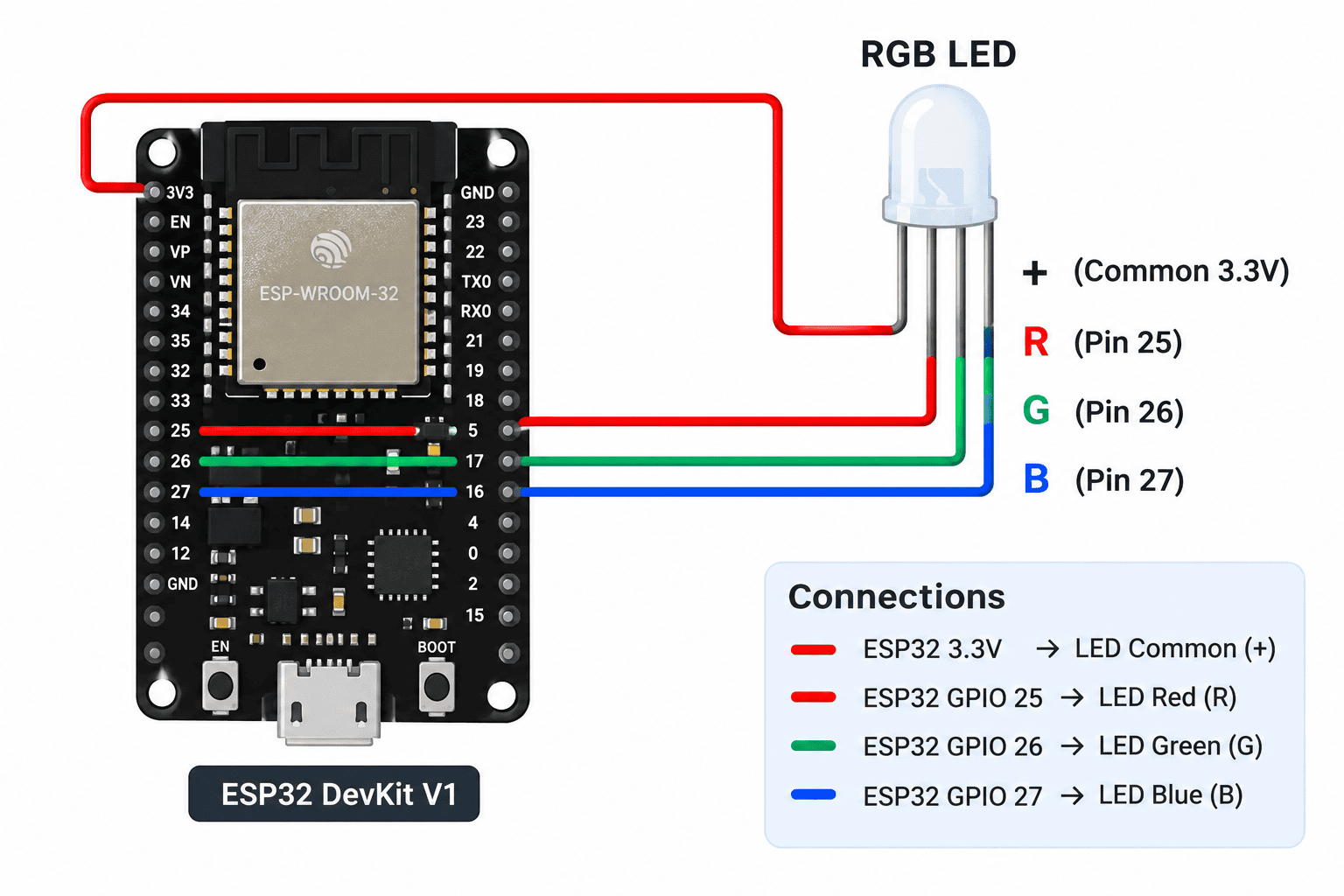
Note: Pay close attention to whether your LED is Common Cathode (shares Ground; HIGH = ON) or Common Anode (shares 3.3V/5V; LOW = ON).
Programming in the Arduino Cloud Editor
The Arduino Cloud Editor is a web-based IDE that automatically syncs your sketches, manages libraries, and features the built-in AI assistant.
How to Program the Arduino Uno (Normal/Non-IoT)
Even without internet connectivity on the board itself, the Cloud Editor is excellent for Uno projects.
- Install the Create Agent: Download and run this background app on your PC so the web browser can communicate with your USB ports.
-
Connect and Select: Plug your Uno in via USB and select it in the Cloud Editor board dropdown.
-
Code & Upload: Write your code in the main window (or use the AI tab to generate it). Click the right-arrow Upload button to compile in the cloud and flash the board over USB.
How to Program the ESP32
The process is identical to the Uno for basic programming. Simply plug the ESP32 in via USB, select the specific ESP32 board model from the dropdown, and upload. Because the Cloud Editor handles the heavy ESP32 core installations in the background, you don’t have to manage complex board manager URLs.
Programming in the Arduino Cloud Editor
The Arduino Cloud Editor is a web-based IDE that automatically syncs your sketches, manages libraries, and features the built-in AI assistant.
How to Program the ESP32
The process is identical to the Uno for basic programming. Simply plug the ESP32 in via USB, select the specific ESP32 board model from the dropdown, and upload. Because the Cloud Editor handles the heavy ESP32 core installations in the background, you don’t have to manage complex board manager URLs.
Deep Dive: Comparing AI Code Outputs
Let’s look at the actual code generated by our AI tools and analyze what they did right, and what they did wrong.
1. ChatGPT’s Arduino Uno Code (Digital / Manual Logic)
/
C++
// Arduino Uno (ChatGPT Output)
// Red -> Pin 2 | Green -> Pin 3 | Blue -> Pin 4

const int RED_PIN = 2;
const int GREEN_PIN = 3;
const int BLUE_PIN = 4;

void setup() {
  pinMode(RED_PIN, OUTPUT);
  pinMode(GREEN_PIN, OUTPUT);
  pinMode(BLUE_PIN, OUTPUT);
}

void loop() {
  // RED
  digitalWrite(RED_PIN, HIGH);
  digitalWrite(GREEN_PIN, LOW);
  digitalWrite(BLUE_PIN, LOW);
  delay(1000);

  // YELLOW = RED + GREEN
  digitalWrite(RED_PIN, HIGH);
  digitalWrite(GREEN_PIN, HIGH);
  digitalWrite(BLUE_PIN, LOW);
  delay(1000);
  // ... (repeats for other colors)
}
Analysis: ChatGPT correctly defined the pins at the top using const int and understood the color mixing math. However, it used standard digitalWrite (which only turns pins hard ON or OFF) and hardcoded delay(1000) into every block. This is a very “brute force” way to code.
2. ChatGPT’s ESP32 Code (Inverted Logic)
C++
// ESP32 COMMON-ANODE RGB LED (ChatGPT Output)
// Red -> GPIO 25 | Green -> GPIO 26 | Blue -> GPIO 27

const int RED_PIN = 25;
const int GREEN_PIN = 26;
const int BLUE_PIN = 27;

void setup() {
  pinMode(RED_PIN, OUTPUT);
  pinMode(GREEN_PIN, OUTPUT);
  pinMode(BLUE_PIN, OUTPUT);

  // Turn all colors OFF when starting (Common Anode = HIGH is OFF)
  digitalWrite(RED_PIN, HIGH);
  digitalWrite(GREEN_PIN, HIGH);
  digitalWrite(BLUE_PIN, HIGH);
}

void loop() {
  // PURPLE = Red + Blue (Inverted logic: LOW = ON)
  digitalWrite(RED_PIN, LOW);      // Red ON
  digitalWrite(GREEN_PIN, HIGH);   // Green OFF
  digitalWrite(BLUE_PIN, LOW);     // Blue ON
  delay(1000);
  // ... (repeats for other colors)
}
Analysis: When prompted that the LED was “Common Anode,” ChatGPT correctly adjusted the logic so that LOW turns the LED on. It even initialized the pins to HIGH in setup() so the LED starts fully off. However, it still used the same brute-force, line-by-line structure as the Uno code.
3. Arduino Cloud AI’s ESP32 Code (PWM & Modular Logic)
C++
// ESP32 RGB LED (Arduino Cloud AI Output)
// Red -> GPIO 25 | Green -> GPIO 26 | Blue -> GPIO 27

const int RED_PIN   = 25;
const int GREEN_PIN = 26;
const int BLUE_PIN  = 27;

// Duration each color is displayed (milliseconds)
const int COLOR_DELAY = 500;

void setup() {
  pinMode(RED_PIN,   OUTPUT);
  pinMode(GREEN_PIN, OUTPUT);
  pinMode(BLUE_PIN,  OUTPUT);
}

// Helper: sets RGB values (0=OFF, 255=full brightness via PWM)
void setColor(int r, int g, int b) {
  analogWrite(RED_PIN,   r);  // Write red intensity
  analogWrite(GREEN_PIN, g);  // Write green intensity
  analogWrite(BLUE_PIN,  b);  // Write blue intensity
}

void loop() {
  setColor(255, 0, 0);       // Red
  delay(COLOR_DELAY);

  setColor(0, 255, 0);       // Green
  delay(COLOR_DELAY);

  setColor(255, 0, 255);     // Magenta (Red + Blue)
  delay(COLOR_DELAY);
}
Analysis: This is significantly better code. The Cloud AI followed the DRY (Don’t Repeat Yourself) principle by creating a setColor() helper function. It also upgraded the logic from simple digitalWrite on/off states to analogWrite PWM (Pulse Width Modulation), allowing you to mix precise values from 0 to 255 for millions of colors. Finally, it parameterized the timing with a COLOR_DELAY variable at the top, so you only have to change one number to adjust the speed of the entire loop.