
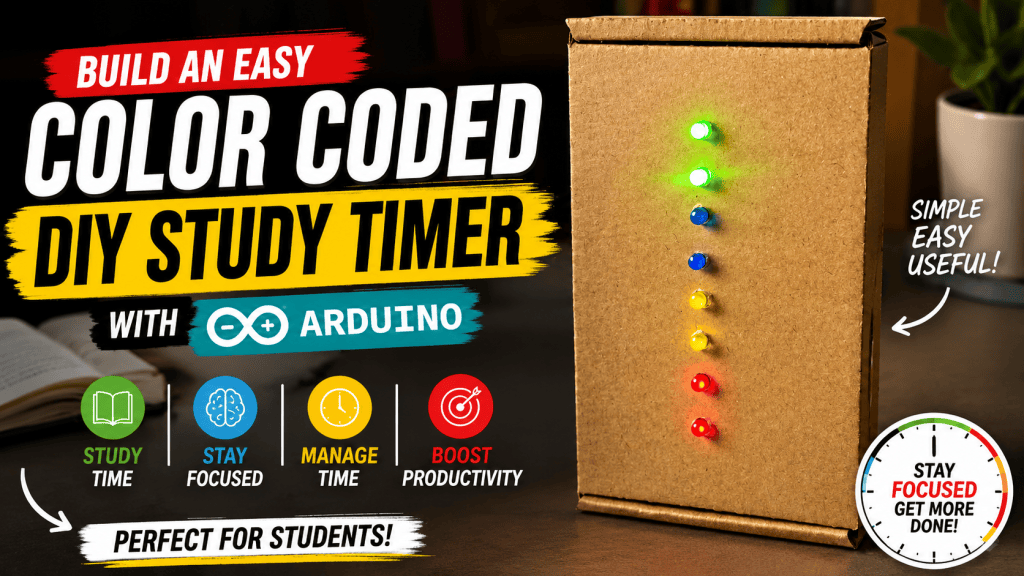
Teaching children about time can be challenging because time is an abstract concept. Saying, “You have five minutes left,” often doesn’t mean much to a young child. They can’t easily visualize how much time remains.
A visual timer solves this problem by replacing numbers with colors. Instead of watching a clock count down, children simply watch the colors change. Green means plenty of time remains, yellow means they’re halfway through, orange reminds them to start finishing up, and flashing red signals that time is almost over.
In this tutorial, you’ll build a simple Arduino-powered Study Timer that uses LEDs to display the remaining time. It’s an excellent beginner project that introduces you to Arduino programming, LEDs, push buttons, breadboards, and timing using the millis() function.
Whether you’re a parent, teacher, student, or someone learning electronics for the first time, this project is both practical and fun to build.
Video Tutorial
If you would like to follow along with the complete build process, watch the accompanying video tutorial before starting.
Features
This study timer has been designed to be simple and intuitive.
| Feature | Description |
|---|---|
| Three Timer Presets | Select 30 seconds, 1 minute, or 2 minutes with dedicated buttons. |
| Color-Coded Progress | LEDs change color as time passes, making the remaining time easy to understand. |
| Visual Warning | The final LED stage flashes during the last 10% of the timer. |
| Automatic Reset | When the timer finishes, all LEDs switch off and the system waits for another button press. |
| Beginner Friendly | Uses only basic Arduino components with no complicated electronics. |
How the Timer Works
Instead of displaying numbers on a screen, this timer divides the selected time into four equal sections.
Each section is represented by a different color.
| Stage | LED Colour | Time Remaining | Behaviour |
|---|---|---|---|
| Stage 1 | 🟢 Green | 100% – 75% | Solid ON |
| Stage 2 | 🟡 Yellow | 75% – 50% | Solid ON |
| Stage 3 | 🟠 Orange | 50% – 25% | Solid ON |
| Stage 4 | 🔴 Red | 25% – 10% | Solid ON |
| Final Warning | 🔴 Red | Last 10% | Flashing |
For example, if you select the 2-minute timer, the Arduino divides those two minutes into four equal 30-second stages. As time passes, the LEDs change colour, giving a clear visual indication of how much time remains.
Bill of Materials
Electronics
| Quantity | Component | Purpose |
|---|---|---|
| 1 | Arduino Uno R3 | The brain of the project. Controls the buttons, LEDs and timer logic. |
| 1 | USB Cable | Used to upload the Arduino sketch and provide power during testing. |
| 1 | 30 Pin Breadboard | Makes it easy to build the circuit without soldering. |
| 8 | Male-to-Male Jumper Wires | Used for connecting the Arduino to the breadboard and buttons. |
| 8 | Male-to-Female Jumper Wires | Used to connect the LEDs mounted in the enclosure to the breadboard. |
| 4 | 220Ω Resistors | Protect the LEDs by limiting the current. |
Push Buttons
| Quantity | Component | Function |
|---|---|---|
| 1 | Green Push Button | Starts the 30-second timer |
| 1 | Yellow Push Button | Starts the 1-minute timer |
| 1 | Red Push Button | Starts the 2-minute timer |
LEDs
| Quantity | Colour | Purpose |
|---|---|---|
| 2 | Green | Stage 1 |
| 2 | Yellow | Stage 2 |
| 2 | Orange (Amber) | Stage 3 |
| 2 | Red | Stage 4 |
Enclosure Materials
| Quantity | Component | Purpose |
|---|---|---|
| 1 | Small Plastic or Cardboard Box | Houses the finished project. |
| 1 | Roll of Prestik (Reusable Adhesive Putty) | Used to secure the Arduino Uno and breadboard inside the box without permanent glue. |
| 1 | Craft Knife or Hobby Knife | Used to cut holes for the LEDs and buttons. (Adult supervision recommended.) |
| 1 | Marker or Pencil | For marking the LED and button positions before cutting. |
| 1 | Ruler | Helps align the LEDs and buttons neatly. |
Understanding the Components
Arduino Uno
The Arduino Uno is the “brain” of the project. It monitors the push buttons, measures elapsed time, and controls which LEDs are turned on.
Think of it as a tiny computer that continuously follows the instructions you upload to it.
Push Buttons
Each button starts a different timer.
| Button Colour | Arduino Pin | Timer |
|---|---|---|
| Green | Pin 2 | 30 Seconds |
| Yellow | Pin 3 | 1 Minute |
| Red | Pin 4 | 2 Minutes |
The Arduino continuously checks these buttons while the program is running.
LEDs
Each colour represents one stage of the countdown.
Two LEDs are used for every colour to make the timer easier to see from across the room.
Each LED group is connected to a separate Arduino digital output.
| LED Group | Arduino Pin |
|---|---|
| Green LEDs | Pin 5 |
| Yellow LEDs | Pin 6 |
| Orange LEDs | Pin 7 |
| Red LEDs | Pin 8 |
The LEDs are connected in series, which allows two LEDs to share the same current while remaining within the safe operating limits of the Arduino output pin.
Wiring Diagram
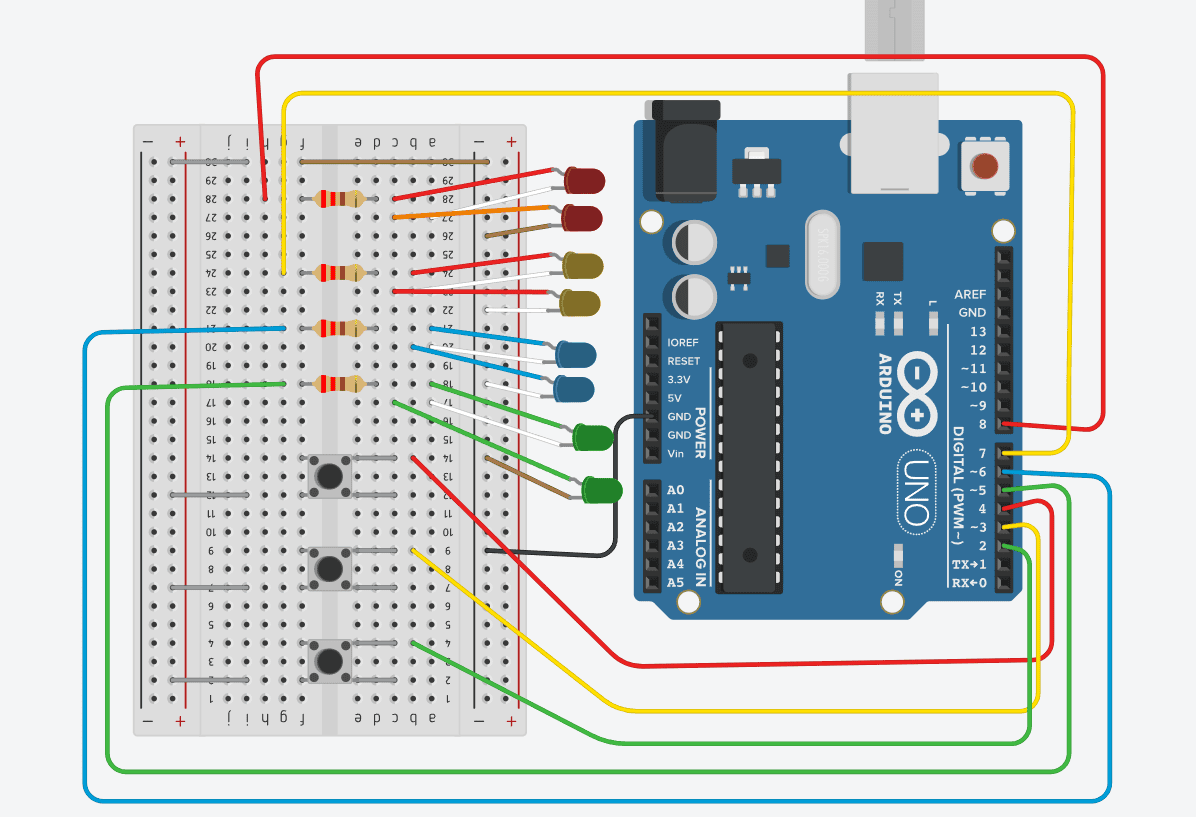
The wiring diagram shows exactly how each LED pair, resistor, and button should be connected.
Building the Enclosure
Once your circuit has been tested on the breadboard, it’s time to turn it into a finished project.
Choose a small cardboard or plastic box that is large enough to hold the Arduino Uno and breadboard comfortably.
Using a ruler and marker, mark the positions for:
- Three push buttons
- Eight LEDs (arranged into four colour groups)
Try to space the LEDs evenly so the timer is easy to read from a distance.
Using a craft knife, carefully cut holes for the LEDs and buttons.
Tip: Make the holes only slightly smaller than the LEDs so they fit tightly without falling out.
Why We Use Male-to-Female Jumper Wires
You may notice that this project uses male-to-female jumper wires instead of connecting the LEDs directly to the breadboard.
This makes the enclosure much easier to assemble.
Instead of mounting the breadboard directly behind the LEDs, each LED is inserted through the front of the box and connected using a female jumper wire.
The female connector simply slides over each LED leg, creating a secure electrical connection without any soldering.
This method has several advantages:
- The LEDs can be mounted neatly in the enclosure.
- The Arduino and breadboard can sit anywhere inside the box.
- The project is much easier to assemble and maintain.
- If an LED ever fails, it can easily be replaced without rebuilding the entire circuit.
The diagram above illustrates how each LED connects to its corresponding female jumper wire.
Mounting the Electronics
Once you’ve confirmed that the circuit works correctly, you can install everything inside the enclosure.
Use small pieces of Prestik to attach:
- the Arduino Uno
- the breadboard
to the bottom of the enclosure.
Prestik is ideal because it holds the components securely while still allowing them to be removed later if you want to modify the project.
Avoid using hot glue unless you are certain you won’t need to move the components in the future.
Installing the LEDs
Insert each LED into its corresponding hole from the outside of the box.
Once inserted, connect the LED legs to the female ends of the male-to-female jumper wires.
The male ends of the jumper wires plug directly into the breadboard according to the wiring diagram.
This approach keeps the wiring neat while allowing the LEDs to be positioned exactly where you want them on the front panel.
Why Are Resistors Needed?
An LED cannot be connected directly to an Arduino output. Without a resistor, too much current flows through the LED, which can permanently damage both the LED and the Arduino. Each LED group therefore uses a 220Ω resistor to safely limit the current.
Why Use Two LEDs Per Colour?
Using two LEDs instead of one makes the timer much easier to see from a distance. This is especially useful in classrooms or when children are sitting several metres away. Connecting the LEDs in series also keeps the current draw low and ensures the Arduino output pin operates safely.
Programming the Arduino
// ==========================================
// CONFIGURATION: Adjust times and pins here
// ==========================================

// Timer durations in milliseconds
const unsigned long TIME_30S = 30000UL;   // 30 seconds
const unsigned long TIME_1M  = 60000UL;   // 1 minute
const unsigned long TIME_2M  = 120000UL;  // 2 minutes

// Button Pins (Input)
const int BTN_30S_PIN = 2; // Green
const int BTN_1M_PIN  = 3; // Yellow
const int BTN_2M_PIN  = 4; // Red

// LED Group Pins (Output)
const int LED_Q1_PIN = 5; // Group 1 (Green)
const int LED_Q2_PIN = 6; // Group 2 (Yellow)
const int LED_Q3_PIN = 7; // Group 3 (Orange)
const int LED_Q4_PIN = 8; // Group 4 (Red)

// Timer State Variables
unsigned long startTime = 0;
unsigned long currentDuration = 0;
bool timerActive = false;

void setup() {

  // Use INPUT_PULLUP:
  // Pin reads HIGH normally, LOW when button is pressed.

  pinMode(BTN_30S_PIN, INPUT_PULLUP);
  pinMode(BTN_1M_PIN, INPUT_PULLUP);
  pinMode(BTN_2M_PIN, INPUT_PULLUP);

  pinMode(LED_Q1_PIN, OUTPUT);
  pinMode(LED_Q2_PIN, OUTPUT);
  pinMode(LED_Q3_PIN, OUTPUT);
  pinMode(LED_Q4_PIN, OUTPUT);

  // Turn all LEDs off at startup
  turnOffAllLEDs();
}

void loop() {

  // Check if any timer button has been pressed

  if (digitalRead(BTN_30S_PIN) == LOW) {
    startTimer(TIME_30S);
    delay(200);   // Simple debounce
  }

  if (digitalRead(BTN_1M_PIN) == LOW) {
    startTimer(TIME_1M);
    delay(200);
  }

  if (digitalRead(BTN_2M_PIN) == LOW) {
    startTimer(TIME_2M);
    delay(200);
  }

  // Update the timer while it is running

  if (timerActive) {
    updateTimerDisplay();
  }
}

//--------------------------------------------
// Start a new timer
//--------------------------------------------

void startTimer(unsigned long duration) {

  currentDuration = duration;
  startTime = millis();
  timerActive = true;

}

//--------------------------------------------
// Update LEDs according to remaining time
//--------------------------------------------

void updateTimerDisplay() {

  unsigned long elapsed = millis() - startTime;

  // Timer finished

  if (elapsed >= currentDuration) {

    timerActive = false;
    turnOffAllLEDs();
    return;

  }

  // Calculate remaining percentage

  float percentRemaining =
      (float)(currentDuration - elapsed) / currentDuration;

  bool q1 = false;
  bool q2 = false;
  bool q3 = false;
  bool q4 = false;

  if (percentRemaining > 0.75) {

    q1 = true;

  }
  else if (percentRemaining > 0.50) {

    q2 = true;

  }
  else if (percentRemaining > 0.25) {

    q3 = true;

  }
  else if (percentRemaining > 0.10) {

    q4 = true;

  }
  else {

    // Flash the red LEDs during the final 10%

    q4 = (millis() / 250) % 2 == 0;

  }

  digitalWrite(LED_Q1_PIN, q1 ? HIGH : LOW);
  digitalWrite(LED_Q2_PIN, q2 ? HIGH : LOW);
  digitalWrite(LED_Q3_PIN, q3 ? HIGH : LOW);
  digitalWrite(LED_Q4_PIN, q4 ? HIGH : LOW);

}

//--------------------------------------------
// Turn all LEDs off
//--------------------------------------------

void turnOffAllLEDs() {

  digitalWrite(LED_Q1_PIN, LOW);
  digitalWrite(LED_Q2_PIN, LOW);
  digitalWrite(LED_Q3_PIN, LOW);
  digitalWrite(LED_Q4_PIN, LOW);

}
Once all of the components have been connected according to the wiring diagram, the Arduino sketch can be uploaded using the Arduino IDE.
One of the most important concepts used in this project is the millis() function.
Unlike delay(), which pauses the entire program, millis() allows the Arduino to keep checking the buttons while simultaneously updating and flashing the LEDs.
This makes the timer much more responsive and is considered one of the best programming techniques for Arduino projects.
How the Program Works
The Arduino repeats the following process hundreds of times every second.
| Step | Action |
|---|---|
| 1 | Wait for a button press |
| 2 | Determine which timer was selected |
| 3 | Record the starting time |
| 4 | Calculate the elapsed time using millis() |
| 5 | Turn on the correct LED group |
| 6 | Flash the red LEDs during the final 10% |
| 7 | Turn all LEDs off when the timer expires |
| 8 | Wait for another button press |
Because the Arduino never stops running, it can respond immediately whenever a new timer is started.
Troubleshooting
| Problem | Possible Cause | Solution |
|---|---|---|
| LEDs do not light | LED polarity reversed | Ensure the long leg (anode) faces the Arduino output and the short leg (cathode) faces GND. |
| One LED pair does not work | One LED installed backwards | Since the LEDs are connected in series, both LEDs must be correctly orientated. |
| Button does nothing | Incorrect wiring | Verify the button is connected to the correct Arduino pin shown in the wiring diagram. |
| Incorrect timer starts | Wrong button connection | Confirm each button is connected to the correct digital input pin. |
| LEDs are dim | Loose connection or incorrect resistor | Check all jumper wires and verify that a 220Ω resistor is used for each LED group. |
Conclusion
This project is an excellent introduction to Arduino because it combines simple electronics with practical programming concepts. Along the way, you’ve learned how to use digital inputs and outputs, control LEDs, read push buttons, use resistors safely, and create non-blocking programs with millis().
Most importantly, you’ve built a useful device that helps children and students develop a better sense of time through clear, intuitive visual feedback. From here, you can continue expanding the project with displays, sound, wireless features, or longer timer presets as your Arduino skills grow.
Troubleshooting
If your study timer isn’t working as expected, don’t worry! Most Arduino projects only require a few simple checks to get them running correctly. Below are the most common problems beginners encounter and how to fix them.
| Problem | Possible Cause | Solution |
|---|---|---|
| Nothing happens when the Arduino is powered on | The Arduino isn’t receiving power or the sketch wasn’t uploaded successfully. | Check that the USB cable is connected securely, the Arduino power LED is on, and the correct board and COM port are selected in the Arduino IDE before uploading the sketch again. |
| The Arduino IDE won’t upload the program | Incorrect board or COM port selected, or another application is using the serial port. | Select Tools → Board → Arduino Uno, choose the correct COM port under Tools → Port, close the Serial Monitor if it’s open, and try uploading again. |
| One LED group doesn’t light up | An LED is inserted backwards, a resistor is missing, or a loose connection exists. | Check the LED polarity. The long leg (anode) should connect towards the Arduino pin through the resistor, and the short leg (cathode) should connect towards Ground. Since the LEDs are wired in series, one reversed LED will prevent both LEDs in that group from lighting. |
| None of the LEDs turn on | Power or Ground is not connected correctly, or the LED pins don’t match the program. | Verify the 5V and GND connections on the breadboard and ensure each LED group is connected to the correct Arduino pin (5–8). |
| A button doesn’t start the timer | Incorrect wiring or loose connection. | Check that the button is connected to the correct digital pin (Pins 2–4) and that the other side of the button is connected to Ground. Ensure the sketch is using INPUT_PULLUP. |
| Pressing one button starts the wrong timer | The buttons are connected to the wrong Arduino pins. | Verify that Green = Pin 2, Yellow = Pin 3, and Red = Pin 4. |
| The LEDs stay on after the timer finishes | The program may not have uploaded correctly or the timer reset logic has been modified. | Upload the original sketch again and ensure the code resets all LED outputs when the timer reaches zero. |
| The LEDs don’t flash during the final warning stage | The flashing section of the code may have been altered or the timer is too short to notice. | Verify that the millis()-based flashing code is present and test using the 2-minute timer, where the flashing period is easier to observe. |
| The timer seems too fast or too slow | Incorrect timer values or changes made to the code. | Check the timer duration variables in the sketch and ensure they are measured in milliseconds (1000 ms = 1 second). |
| LEDs are very dim | Incorrect resistor value, poor breadboard connections, or low-quality LEDs. | Confirm that you’re using approximately 220Ω resistors, check all jumper wire connections, and replace any faulty LEDs if necessary. |
| Only one LED lights in a pair | One LED may be faulty or incorrectly installed. | Test each LED individually and verify that both LEDs are connected in the correct orientation. |
| The Arduino keeps resetting | A short circuit or incorrect wiring is causing the Arduino to restart. | Disconnect the power immediately and carefully compare your circuit with the wiring diagram. Check for wires touching where they shouldn’t and ensure no components are shorting 5V to Ground. |
Beginner Tips
If you’re still having trouble, these simple checks solve most Arduino issues:
- ✔ Double-check every wire against the wiring diagram.
- ✔ Make sure every LED is facing the correct direction.
- ✔ Ensure every LED group has its own 220Ω resistor.
- ✔ Verify that the correct Arduino board and COM port are selected before uploading.
- ✔ Upload the original sketch before making any code modifications.
- ✔ If something still doesn’t work, disconnect the power and inspect your breadboard one connection at a time instead of changing multiple things at once.
Tip: Electronics troubleshooting is a normal part of every project—even experienced makers rarely get a circuit working perfectly on the first attempt. Working through problems methodically is one of the best ways to learn Arduino and electronics.