
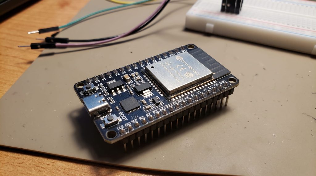
Whether you are an engineering student building your final year project or a hobbyist looking to automate your home, the ESP32 is the undisputed king of modern DIY electronics.
But graduating from a basic Arduino Uno to an ESP32 can be jarring. The ESP32 is incredibly powerful, but it has complex power requirements, a tricky pinout, and a steeper learning curve when getting it online. Think of this blog as your ultimate technical manual—bookmark it, because you will need it when building your projects.
Introduction: What is the ESP32?
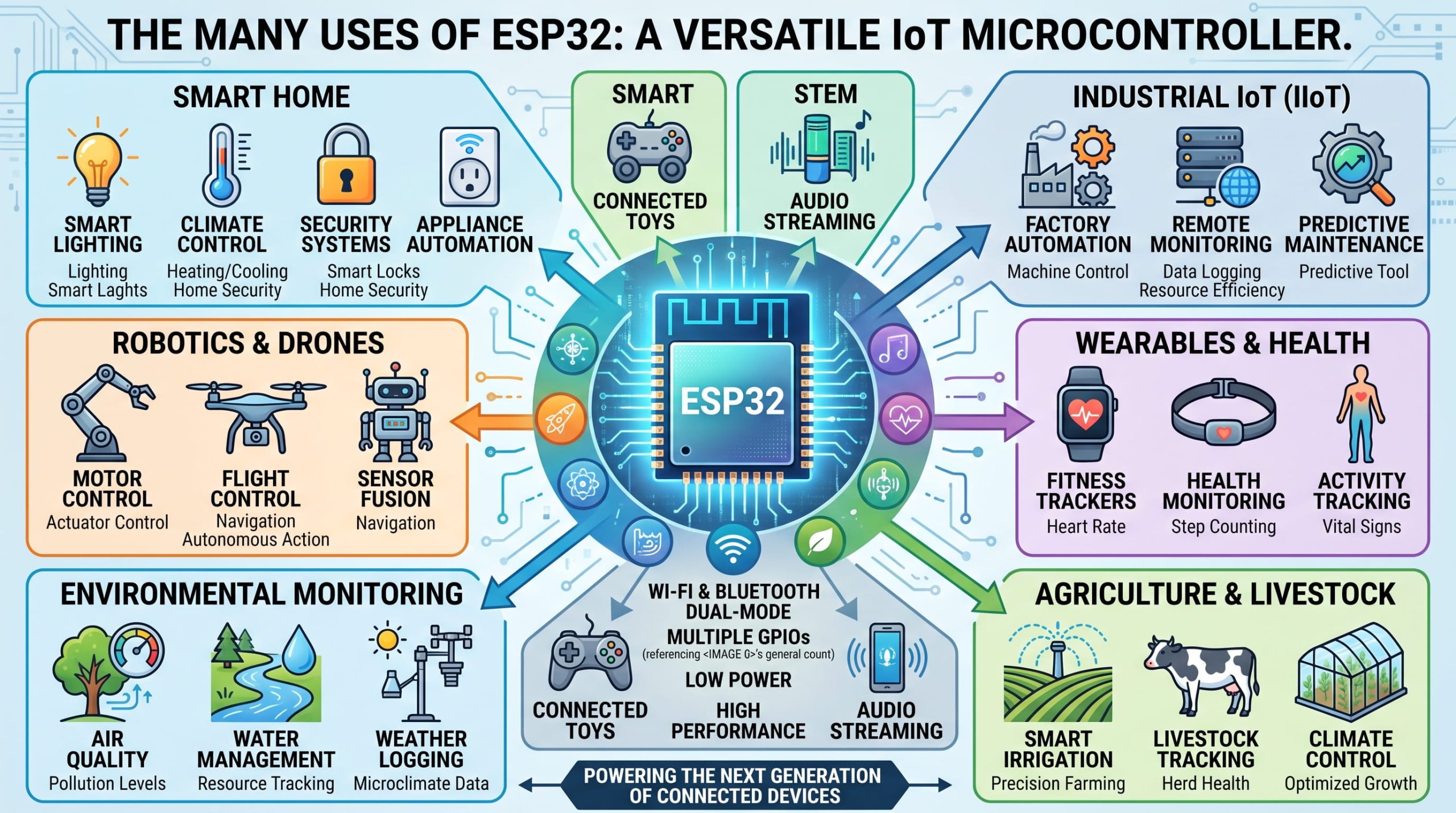
The ESP32 is a low-cost, low-power System on a Chip (SoC) created by Espressif Systems. It is a microcontroller—a tiny computer designed to read sensors and control hardware—but it completely revolutionized the maker movement by integrating Wi-Fi and dual-mode Bluetooth directly into the silicon.
Before the ESP32, if you wanted an Arduino to connect to the internet, you had to buy expensive, clunky Ethernet or Wi-Fi “shields.” The ESP32 solved this by offering vastly more computing power and built-in connectivity for roughly $5.
Beyond smart home IoT, it is heavily used as a standalone web server, a brain for robotics, and in industrial sensor networks.
Core Hardware & The ESP Family
Let’s look under the hood. The classic ESP32 (often labeled ESP-WROOM-32) operates at 3.3 Volts (unlike the 5V Arduino Uno) and packs serious hardware.
- Processor: A Tensilica Xtensa 32-bit LX6 dual-core processor running at 160 or 240 MHz. (For context, an Arduino Uno runs on a single core at 16 MHz).
- Memory: 520 KB of internal SRAM, typically paired with 4MB of external SPI Flash memory to store your code.
- Wireless: 802.11 b/g/n Wi-Fi and dual-mode Bluetooth (Classic and Bluetooth Low Energy / BLE).
The Modern ESP32 Variants
The Modern ESP32 Variants & Development Kits
The Chip vs. The Module vs. The Dev Kit
-
The SoC (System on a Chip): This is the raw black silicon square. It contains the processor and memory. Unless you are a factory printing your own custom circuit boards, you will never buy just the SoC.
-
The Module (e.g., ESP-WROOM-32): This is the small, stamp-sized circuit board with the castellated (half-moon) edges and a shiny metallic shield on top. The module takes the SoC, pairs it with an antenna and flash memory, and wraps it in a metal shield to pass FCC radio interference regulations.
-
The Dev Kit (Development Kit): This is what you actually buy as a student or hobbyist. A Dev Kit takes the stamp-sized Module and solders it onto a larger circuit board with male header pins. It adds a USB port, a voltage regulator (to step 5V USB power down to the 3.3V the chip needs), and a USB-to-Serial bridge chip (so your computer can talk to it).
The Modern ESP32 Variant Lineup
| Variant Series | Architecture | Key Features | Best Used For |
| ESP32 (Classic) | Xtensa Dual-Core | Wi-Fi 4, Bluetooth Classic & BLE, 240 MHz. | General purpose IoT, legacy Bluetooth audio streaming. |
| ESP32-S2 | Xtensa Single-Core | Wi-Fi 4, Native USB OTG. (No Bluetooth) | Projects acting as a USB mouse/keyboard. |
| ESP32-S3 | Xtensa Dual-Core | Wi-Fi 4, BLE 5, Native USB, AI/Vector Acceleration. | Smart displays, voice recognition, AI cameras (e.g., ESP32-S3-CAM). |
| ESP32-C3 | RISC-V Single-Core | Wi-Fi 4, BLE 5, Low Cost, Ultra-Low Power. | Simple, battery-powered sensor nodes and budget IoT devices. |
| ESP32-C6 | RISC-V Single-Core | Wi-Fi 6, BLE 5.3, Zigbee & Thread. | Modern Smart Home devices requiring “Matter” integration and dense network performance. |
| ESP32-P4 | RISC-V Dual-Core | 400 MHz, H.264 Video Encoder, MIPI Camera/Display. (No Wireless) | High-performance multimedia, touch screens, and intense data processing. |
Choosing a Dev Kit for Low-Power & Specific Uses
-
Standard Prototyping (DOIT DevKit V1 / NodeMCU-32S): These are the generic 30-pin or 38-pin boards. They are cheap and great for breadboard testing on USB power, but they are terrible for battery life because their cheap voltage regulators constantly leak power, even in deep sleep.
-
Low-Power & Battery Projects (DFRobot FireBeetle / TinyPICO): If you want a battery to last months, you need a specially designed low-power Dev Kit. Boards like the FireBeetle ESP32 or Adafruit Huzzah32 use high-efficiency voltage regulators and include built-in LiPo battery connectors with charging circuits. Pair these with an ESP32-C3 or C6 chip, put it into “deep sleep,” and your board will sip merely ~5 to 40 µA (microamps) of power while idle.
-
Ultra-Compact Wearables (Seeed Studio XIAO ESP32 Series): These Dev Kits are the size of a postage stamp. They break out only the essential 11 pins but easily fit inside tiny 3D-printed enclosures for wearables or hidden sensors.
-
Vision Projects (ESP32-CAM): A specialized Dev Kit featuring an OV2640 camera module and a microSD card slot. Warning: Most ESP32-CAM boards lack a built-in USB port to save space, meaning you need an external “FTDI programmer” to upload your code!
How to Visually Recognize Your Board
-
Read the Silver Shield: The metallic square on the board has the variant laser-etched onto it. If it says
ESP32-WROOM-32, it’s the classic. If it saysESP32-S3-MINIorESP32-C3-WROOM, you immediately know your variant. -
Check the USB Port Type:
-
Micro-USB: Usually indicates an older, classic ESP32 Dev Kit.
-
USB-C: Found on newer S2, S3, C3, and C6 Dev Kits.
-
-
Count the Pins: A standard ESP32 DevKitC has 38 pins (19 down each side). A classic NodeMCU-32S has 30 pins. If it has very few pins (e.g., 14 total), it is likely an ultra-compact board like an ESP32-C2 or a XIAO board.
-
Look for the Battery Port: A small white plastic block (JST connector) near the edge of the board means it’s a battery-ready Dev Kit (like a FireBeetle or Huzzah), making it ideal for low-power remote deployments.
The Definitive ESP32
Pinout Guide

When you buy a standard 38-pin ESP32 development board, it comes with male headers. You will need a breadboard and female-to-male jumper wires to connect external components.
The ESP32 features a peripheral multiplexing matrix, meaning almost any digital pin can be configured via code to handle PWM (fading), I2C, or SPI. However, not all pins are safe to use.
The ESP32 is a phenomenal microcontroller, but its pinout can be a minefield for beginners. Unlike simpler boards where almost every pin acts the same, the ESP32’s advanced architecture means that choosing the wrong pin can cause your code to fail, your sensors to act erratically, or your board to refuse to boot completely.
If you are building a project, this guide is your survival manual. Here is a deep dive into the ESP32 pins, what they do, and which ones you should actually use.
The “Safe” GPIO Pins (Use These First!)
If you want to blink an LED, trigger a relay, or read a basic digital sensor, you want to use pins that have no hidden catches or boot-up quirks.
The absolute safest GPIO pins to use are:
-
GPIO: 16, 17, 18, 19, 21, 22, 23, 25, 26, 27, 32, and 33.
You can configure any of these as standard inputs (to read buttons) or standard outputs (to light LEDs) without worrying about crashing your board.
Note: GPIO 34, 35, 36, and 39 are also perfectly safe, but they are Input-Only. You can use them to read sensors, but they physically cannot output voltage to turn on an LED.
- Note: I2C communication defaults to GPIO 21 (SDA) and GPIO 22 (SCL).
Pin Numbers vs. GPIO Numbers (and the “D” Prefix)
One of the biggest sources of confusion is how pins are labeled on the physical board versus how they are called in your code.
-
The Physical Pin Number: This is literally the pin’s physical location on the board (e.g., “Pin 1” at the top left, “Pin 2” below it). You never use physical pin numbers in your Arduino code.
-
The GPIO Number (General Purpose Input/Output): This is the internal numerical address that the ESP32 processor uses. When you write
pinMode(4, OUTPUT);, you are telling the processor to activate GPIO 4. -
The “D” Prefix (e.g., D4, D13): On many development boards, you will see pins labeled as
D4orD13. The “D” simply stands for Digital. Thankfully, on the ESP32, theDnumber almost always matches theGPIOnumber. So, if the silk-screen printed on your board saysD4, you will refer to it as just4in your code.
The “Strapping Pins” (The Danger Zone)
If your ESP32 randomly refuses to let you upload code, or it fails to boot up when you plug it in, you have likely connected something to a Strapping Pin. The ESP32 has five strapping pins: GPIO 0, 2, 5, 12, and 15.
When the ESP32 first receives power, it spends a split second checking the voltage levels (HIGH or LOW) on these specific pins to decide how it should boot up. For example, it checks if it should run the program you wrote, or if it should enter “flashing mode” to wait for new code via USB.
-
The Problem: If you connect a sensor or a pull-up resistor to one of these pins, you might accidentally force the pin HIGH or LOW during boot. The ESP32 gets confused, enters the wrong boot mode, and appears “dead”.
-
The Rule: Avoid using GPIO 0, 2, 5, 12, and 15 unless you absolutely have to. If you must use them, only connect components (like LEDs) that won’t interfere with the pin’s voltage during the split-second boot-up phase.
(There are also the “Deadly Pins”—GPIO 6 through 11. These are internally connected to the flash memory chip that stores your code. If you connect anything to them, the board will instantly crash.)
Special Function Pins: ADC, TX, and RX
While the ESP32 has a multiplexer that allows you to assign functions to almost any pin, some pins have dedicated, hardwired hardware inside the chip.
ADC Pins (Analog to Digital Converter)
The real world isn’t just digital ON/OFF (1s and 0s); it is analog. Analog pins can read a range of varying voltages, which is essential for reading temperature sensors, photoresistors (light sensors), or volume knobs.
-
The ESP32 can translate voltages between 0V and 3.3V into a digital number between 0 and 4095.
-
Which to use: Always try to use ADC1 pins (GPIO 32, 33, 34, 35, 36, 39). As mentioned previously, the ADC2 pins will fail to read analog data if you turn on the ESP32’s Wi-Fi.
TX and RX Pins (UART / Serial Communication)
TX (Transmit) and RX (Receive) are used for UART Serial communication—how the ESP32 talks to your computer, GPS modules, or other microcontrollers.
-
TX0 (GPIO 1) and RX0 (GPIO 3): These are hardwired to the USB port. This is how the Arduino IDE uploads code and displays messages in the Serial Monitor. Never use these for normal components, or you will break your ability to debug your code.
-
If you need to connect a serial device (like a GPS), use the secondary hardware serial port: TX2 (GPIO 17) and RX2 (GPIO 16).
The EN and BOOT Pins
Finally, near the edges of the board or next to the physical push buttons, you will see the EN and BOOT pins.
-
EN (Enable): This is the hardware reset pin for the ESP32’s 3.3V regulator. Pulling this pin to Ground (
GND) shuts off the ESP32. Releasing it turns the chip back on. The physical “Reset” button on your board is just a switch connected to this EN pin. -
BOOT (GPIO 0): This is the master strapping pin. When you hold the physical BOOT button down while the board resets, you force GPIO 0 to a LOW state. This tells the ESP32, “Don’t run the current code; wait for new code over the USB cable”. If your Arduino IDE ever gets stuck saying “Connecting…” during an upload, holding down the BOOT button forces it into the correct mode.
Arduino vs. ESP32: The “Blink” Example
Because the ESP32 can be programmed using the Arduino IDE, the core C++ logic (void setup() and void loop()) is identical to an Arduino Uno. The difference lies in the hardware execution.
If you want to blink an LED:
- Arduino Uno: You connect the LED to Pin 13 and GND. You output 5V.
- ESP32: You connect the LED to a safe GPIO (e.g., GPIO 16) and GND. You output 3.3V.
Use the following code comparison to see how the syntax adapts between the two boards:
Arduino Code
// Arduino Uno - Blink LED
const int LED_PIN = 13; // Built-in LED on Pin 13

void setup() {
  pinMode(LED_PIN, OUTPUT);
}

void loop() {
  digitalWrite(LED_PIN, HIGH); // Set pin to 5V
  delay(1000);
  digitalWrite(LED_PIN, LOW);  // Set pin to 0V
  delay(1000);
}
- Uses standard Pin 13 (Built-in LED).
- Logic Voltage: 5V tolerant outputs.
- Simple digital I/O syntax with hardware timers
ESP32 Code
// ESP32 - Blink LED
const int LED_PIN = 16; // Using GPIO 16

void setup() {
  pinMode(LED_PIN, OUTPUT);
}

void loop() {
  digitalWrite(LED_PIN, HIGH); // Set pin to 3.3V
  delay(1000);
  digitalWrite(LED_PIN, LOW);  // Set pin to 0V
  delay(1000);
}
- Uses GPIO 16 mapping for external LED.
- Logic Voltage: Strict 3.3V logic (NOT 5V tolerant!).
- FreeRTOS handles delay() under the hood, allowing multi-tasking.
Crucial Warning: The ESP32 is strictly a 3.3V device. If you use a 5V sensor (like an ultrasonic distance sensor originally meant for Arduino), connecting its 5V output directly to an ESP32 input pin will likely destroy the pin. You must use a Logic Level Shifter circuit to step the 5V signal down to 3.3V.
Setting up the Arduino IDE for ESP32
To program the ESP32, you need to prepare the Arduino IDE. It doesn’t support ESP32 out of the box.
Board > Boards Manager. Search for “esp32” by Espressif Systems and click Install. This downloads the compilers and core libraries.
Go to Tools > Board and select your specific board. If you have a generic 38-pin board, select “ESP32 Dev Module”or “DOIT ESP32 DEVKIT V1” .
Select the COM port that appeared after installing your drivers.
Go to Sketch > Include Library > Manage Libraries. Here you can search for and install libraries needed for your specific hardware (like the DHT11 temperature sensor) or cloud platforms (like Blynk).
- Going Wireless: ESP-NOW and Web Servers
Before jumping to the cloud, you should know the ESP32 can operate completely offline while still being wireless:
- Standalone Web Server: The ESP32 can host an HTML/CSS webpage directly from its memory (using the ESPAsyncWebServer library). You connect your phone to the ESP32’s local Wi-Fi, open a browser, and click buttons to trigger GPIO pins.
- ESP-NOW: This is Espressif’s custom protocol. It allows multiple ESP32 boards to talk directly to each other via their MAC addresses using a 2.4GHz signal, completely bypassing your Wi-Fi router. It is lightning-fast and perfect for remote control cars or multi-sensor networks.
Cloud Platforms: Arduino IoT Cloud vs Blynk
For true IoT, you need a cloud broker. This allows you to monitor your ESP32 from the other side of the world. Here are the detailed workflows for the two most popular platforms.
Workflow A: Arduino IoT Cloud
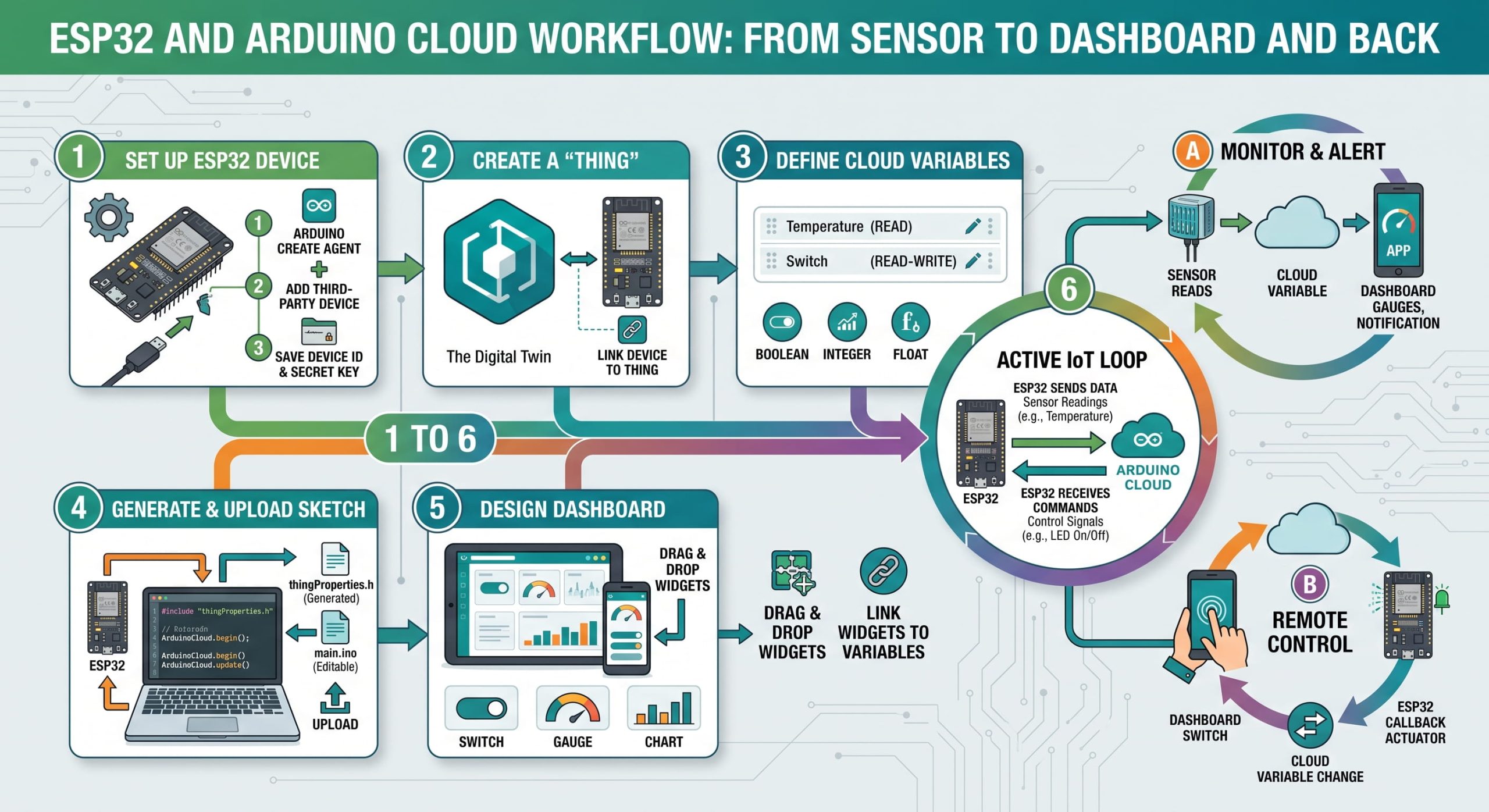
Arduino Cloud generates network code for you automatically. It’s excellent for students who want to focus on hardware logic rather than backend web development.
1.Install the Create Agent:
Sign up at cloud.arduino.cc. Download and run the Arduino Create Agent in the background on your PC. This allows the web browser to talk to your ESP32 via USB.
2.Create a Device:
In the Devices tab, click “Add Device” -> “Third Party Device” -> “ESP32”. Follow the prompts to configure it and note the Secret Key provided.
3.Create a Thing and Variables:
Create a “Thing” (the project container). Click “Add Variable”.
- For a light switch, name it cloudSwitch (Type: Boolean, Read & Write).
- For a sensor, name it cloudTemp (Type: Float, Read Only).
- Enter your Wi-Fi credentials in the Network tab.
4.Edit the Auto-Generated Sketch:
Go to the Sketch tab. Arduino Cloud automatically generates your main .ino file and a hidden thingProperties.h file. You will see ArduinoCloud.begin() in the setup, and ArduinoCloud.update() in the loop. You just add your logic (e.g., if (cloudSwitch) { digitalWrite(16, HIGH); }).
5.Build the Dashboard:
Go to Dashboards, create a new one, and drag-and-drop a Switch widget. Link it to your cloudSwitch variable. Upload the code via the web editor.
Workflow B: Blynk IoT
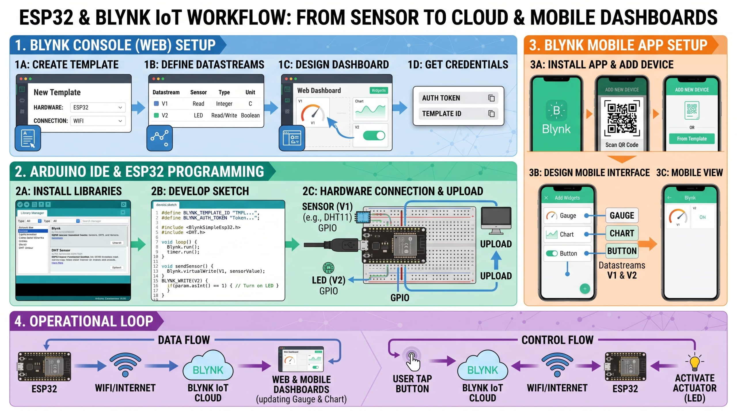
Blynk is industry-standard for mobile-first deployments. It uses a “Virtual Pin” system, which separates hardware pins from cloud data streams.
1.Create a Template and Datastreams:
In the Blynk web console, create a Template (Hardware: ESP32, Connection: WiFi). Navigate to Datastreams. Create a Virtual Pin.
- Assign Virtual Pin V0 as an Integer for an LED switch.
- Assign Virtual Pin V1 as a Double for temperature.
2.Add a Device:
Go to the Search/Devices tab and add a new device based on your Template. Blynk will generate a block of code containing your BLYNK_TEMPLATE_ID and BLYNK_AUTH_TOKEN.
3.Configure the Arduino IDE Sketch:
Install the “Blynk” library in your Arduino IDE. Paste the Auth Token and Wi-Fi credentials at the top of your sketch.
4.Code the Virtual Pins:
To send data to the cloud, use: Blynk.virtualWrite(V1, temperatureData);.
To receive data from a cloud button on V0, create a dedicated function outside your loop:
BLYNK_WRITE(V0) { int pinValue = param.asInt(); digitalWrite(16, pinValue); }
5.Build the Mobile App:
Download the Blynk app on your phone, log in, and drag a button widget onto your device screen. Assign it to Datastream V0.
Troubleshooting Guide & FAQ
ESP32 development can be frustrating when things go wrong. Here are the most common errors and how to fix them:
- Error: “A fatal error occurred: Failed to connect to ESP32: Timed out waiting for packet header”
- The Fix: When the Arduino IDE console says “Connecting…”, hold down the physical BOOT button on your ESP32 board until the upload starts. To fix this permanently, solder a 10µF capacitor between the EN pin and the GND pin.
- Error: “Brownout detector was triggered”
-
- The Fix: The ESP32 is drawing more power than your USB port can provide, causing the voltage to dip and the chip to reset safely. Try a different USB port, a shorter/thicker USB cable, or power the VIN pin using a dedicated 5V 2A power supply.
-
- Issue: No COM Port appears in the Arduino IDE
- The Fix: You are likely using a “Charge-Only” micro-USB cable that lacks data wires, or you forgot to install the CH340 / CP210x drivers.
- Issue: Analog sensor reads 0 constantly when connected to Wi-Fi
- The Fix: You accidentally connected the sensor to an ADC2 pin (like GPIO 4 or 27). Move it to an ADC1 pin (like GPIO 34) and update your code.
Buying Guide: What to Look For
If you are buying an ESP32 for a project, keep these factors in mind:
- Pin Count: Standard boards have 30 or 38 pins. 38-pin boards expose more GPIOs but can be wider, sometimes covering all the holes on a standard breadboard (requiring you to straddle two breadboards).
- USB Connector: Look for boards that have upgraded to USB-C rather than fragile Micro-USB.
- Antenna: Most boards use a squiggly trace on the PCB as an antenna. If your project is outdoors or far from a router, look for a board with an IPEX connector (often labeled ESP32-WROOM-32U) so you can attach a large external antenna.
- Battery Support: If your project runs on batteries, buy a board like the FireBeetle ESP32 or Adafruit Huzzah32. These have built-in JST connectors and charging circuits for 3.7V LiPo batteries, automatically recharging them when plugged into USB.