
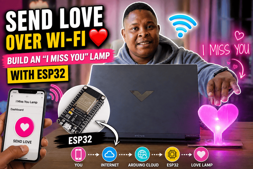
Control a real light from your phone—even when you’re miles away. Imagine pressing a button on your phone and having a lamp in your bedroom light up. Now imagine that the lamp is in another city—or even another country. That’s exactly what we’re going to build in this beginner-friendly ESP32 project.
We’ll create an internet-connected “I Miss You” lamp using an ESP32, an RGB LED and Arduino Cloud. When someone presses a button on a phone, the ESP32 receives the command over the internet and makes the RGB LED pulse.
Watch full video below
You could use the same idea for much more than sending an “I Miss You” message:
- Let someone know you’re thinking about them.
- Send a signal that dinner is ready.
- Create a remote doorbell.
- Build a notification light for your desk.
- Create a simple IoT alarm.
- Turn appliances or lights on and off remotely.
- Build the foundation for a smart-home project.
This project is particularly useful because it introduces one of the most important ideas in modern electronics:
A microcontroller doesn’t have to be physically connected to your phone to receive instructions from it.
The ESP32 can connect to the internet using Wi-Fi, allowing your phone and the ESP32 to communicate through Arduino Cloud.
What We’re Going to Build
Our finished system will look roughly like this:
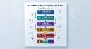
When you press the button on the Arduino Cloud dashboard, a Boolean variable changes from false to true.
The ESP32 notices the change and runs an animation.
The RGB LED then pulses five times before turning off again.
You don’t need to understand everything about the internet or cloud computing to build this project. We’ll learn each part step by step.
What You Will Need
Electronics
For the basic project, you’ll need:
- ESP32 development board
- RGB LED
- Breadboard
- 6x F-F Jumper wires
- USB data cable
- Computer
You’ll also need a Wi-Fi network with internet access.
Software
We’ll use:
- Arduino IDE — to test and program the ESP32 locally.
- Arduino Cloud — to connect the ESP32 to the internet and create our phone-accessible control dashboard.
The Arduino Cloud platform supports compatible ESP32 and ESP8266 boards, while the Cloud Editor can upload sketches through the Arduino Cloud Agent.
Before We Start: What Is an ESP32?
If you’ve used an Arduino Uno before, you can think of the ESP32 as a more powerful cousin. An Arduino Uno is excellent for learning electronics and controlling sensors, motors and LEDs. You can also view our ESP32 guide to help you get started.
The ESP32 can do those things too, but it also includes built-in:
- Wi-Fi
- Bluetooth
- Much more processing power
- More memory
- Many GPIO pins
- PWM capabilities
- Support for IoT applications
The important feature for this project is Wi-Fi.
The ESP32 will connect to your Wi-Fi network and use that internet connection to communicate with Arduino Cloud.
This is what turns a simple LED project into an Internet of Things (IoT) project.
Part 1: Install Arduino IDE
Before connecting the ESP32 to Arduino Cloud, let’s make sure we can program it normally.
This is an important beginner step.
You don’t want to troubleshoot Wi-Fi, Arduino Cloud and your hardware all at the same time.
First, we’ll prove that:
Computer → USB cable → ESP32
is working correctly.
Step 1: Download Arduino IDE
Download and install the latest Arduino IDE for your computer.
The Arduino IDE is the program we’ll use to write, compile and upload code to the ESP32.
Once installed, open it.
You should see a window where you can create a new sketch.
Part 2: Add ESP32 Support to Arduino IDE
The Arduino IDE doesn’t automatically know how to program every ESP32 board.
We therefore need to install the ESP32 board package.
A board package contains the software Arduino IDE needs to compile and upload programs for a particular family of boards.
Espressif, the company behind the ESP32, provides the Arduino-ESP32 board package.
Step 1: Open Preferences
In Arduino IDE:
Windows/Linux:
File → Preferences
macOS:
Arduino IDE → Settings
Look for:
Additional boards manager URLs
Arduino’s current instructions place this setting inside the Preferences/Settings window.
Paste this URL:
https://espressif.github.io/arduino-esp32/package_esp32_index.json
If you already have another URL in this box, don’t delete it. Add the ESP32 URL as another entry.
Click OK.
Part 3: Install the ESP32 Board Package
Now we need to install the actual ESP32 software package.
Go to:
Tools → Board → Boards Manager
In the search box, type:
esp32
Look for:
esp32 by Espressif Systems
Click Install.
The installation may take a few minutes.
Once it has finished, Arduino IDE will be able to compile programs for ESP32 boards.
Part 4: Connect Your ESP32
Connect your ESP32 to your computer using a USB cable.
Important: Your USB cable must carry data
Some USB cables are designed only for charging.
If the ESP32 powers up but your computer cannot see it, try another cable.
You should see an LED on the ESP32 turn on when it receives power.
Part 5: Select Your ESP32 Board
In Arduino IDE, open:
Tools → Board
Look for:
ESP32 Arduino
You will see a list of different ESP32 boards.
Select the board that matches your hardware.
For example, many inexpensive ESP32 development boards are based on the ESP32 DevKit V1.
If you aren’t sure which board you have, check the writing printed on the board or the documentation supplied by the manufacturer.
If your exact board isn’t listed, Espressif also provides generic ESP32 development-module options for supported chips.
A note about board selection
Selecting the wrong board can cause compilation or upload problems.
For example, an ESP32, ESP32-S2 and ESP32-S3 are different chips and should not automatically be treated as the same board.
For beginners, the safest approach is:
Find the exact board model first, then select the closest matching option in Arduino IDE.
Part 6: Find the ESP32’s COM Port
Your computer communicates with the ESP32 through a serial/USB connection.
On Windows, this normally appears as something like:
COM3
COM4
COM7
On macOS or Linux, the name will look different.
Go to:
Tools → Port
and select the port belonging to your ESP32.
How do I know which port is my ESP32?
If you’re unsure:
- Disconnect the ESP32.
- Look at the available ports.
- Connect the ESP32.
- Open the Port menu again.
- Select the newly appearing port.
If no new port appears, you may need the appropriate USB-to-serial driver for your particular ESP32 board.
Different ESP32 development boards use different USB interface chips, so don’t assume every board uses CP210x. Some use CH340/CH341 or other USB interfaces.
Arduino also recommends using Arduino IDE to install the appropriate board package when an ESP32 isn’t detected correctly by Arduino Cloud, because this can install required drivers/configuration files on some systems.
Part 7: Your First ESP32 Program
Before we connect anything to the internet, let’s perform a simple test.
This is the electronics equivalent of saying:
“Hello, computer. Can you hear me?”
We’ll make the ESP32’s onboard LED blink.
Many ESP32 development boards use GPIO 2 for their onboard LED, although this is not universal. If your board uses a different LED pin, check its documentation.
For a common ESP32 DevKit board, try:
const int LED_PIN = 2;

void setup() {
  pinMode(LED_PIN, OUTPUT);
}

void loop() {
  digitalWrite(LED_PIN, HIGH);
  delay(1000);

  digitalWrite(LED_PIN, LOW);
  delay(1000);
}
Let’s understand the code.
const int LED_PIN = 2;
We’re creating a variable called LED_PIN.
It contains the number:
2
This tells our program which GPIO pin we’re using.
setup()
void setup()
runs once when the ESP32 starts.
We use it to configure the board.
pinMode()
pinMode(LED_PIN, OUTPUT);
tells the ESP32:
“We’re going to use this pin to control something.”
loop()
void loop()
runs repeatedly.
The ESP32 continuously goes through this section:
- Turn LED on
- Wait
- Turn LED off
- Wait
- Repeat
Part 8: Upload the Program
Click the Upload button in Arduino IDE.
Arduino will first compile the program.
Compilation means converting your human-readable Arduino code into machine instructions that the ESP32 can execute.
The IDE will then upload those instructions to the ESP32.
If everything works, your onboard LED should blink approximately once every second.
If the upload doesn’t work
Don’t panic.
ESP32 boards sometimes require you to press and hold the BOOT button while the upload begins. The exact behavior depends on the board.
Also check:
- The correct board is selected.
- The correct COM port is selected.
- The USB cable supports data.
- No other program is using the COM port.
- The ESP32 is connected directly to the computer.
- The required board package is installed.
Espressif’s documentation notes that some boards may require the BOOT button during uploading.
Important troubleshooting tip
If Arduino IDE is open and you’re trying to upload using Arduino Cloud, close Arduino IDE first. Only one application should normally be communicating with the ESP32’s serial port at a time.
Part 9: Understanding What We’ve Achieved
At this point, we haven’t used Wi-Fi yet. We’ve proved that the computer can communicate with the ESP32 and that the ESP32 can execute our program.
Now we’re ready for the exciting part. We’re going to replace the computer connection with an internet connection.
Part 10: What Is Arduino Cloud?
Arduino Cloud is an online platform that allows you to create, program and monitor connected devices.
For this project, it gives us three important things:
- A place to manage our ESP32
Arduino Cloud knows which physical ESP32 belongs to our project. - Internet communication
The ESP32 connects to Wi-Fi and communicates with Arduino Cloud. - A dashboard
We can create a button that can be accessed from a browser or phone.
Part 11: Create an Arduino Cloud Account
Go to the Arduino Cloud website and create an account.
Arduino Cloud provides both cloud-based programming and IoT functionality.
Once you’re logged in, you’ll see the Arduino Cloud dashboard.
Don’t worry if it looks unfamiliar.
We’ll only use a few important sections.
Part 12: Install the Arduino Cloud Agent
Because we’re going to upload a program from the browser to a physical ESP32 connected to your computer, the browser needs a way to communicate with the USB device.
This is where the Arduino Cloud Agent comes in.
The Cloud Agent is a small application that runs on your computer and allows Arduino Cloud to communicate with compatible boards connected through USB.
Arduino states that the Cloud Agent is required for uploading sketches through the Cloud Editor on supported desktop systems.
When Arduino Cloud asks you to install the Agent:
- Download it.
- Install it.
- Allow it to run.
- Return to your browser.
- Refresh the Arduino Cloud page if necessary.
Part 13: Add Your ESP32 to Arduino Cloud
Now we need to tell Arduino Cloud:
“This ESP32 belongs to me and I want to use it with my project.”
Go to:
Devices
Click:
Add Device
For a third-party ESP32, choose:
Compatible device
Then choose:
ESP32
Arduino Cloud’s current device setup uses this process for compatible third-party ESP32 and ESP8266 boards.
Give your device a name.
For example:
I Miss You Lamp ESP32
Arduino Cloud will generate device credentials.
You may receive:
- Device ID
- Secret Key
VERY IMPORTANT: Save Your Secret Key
Save the Secret Key somewhere safe.
The Secret Key is essentially a credential that allows your ESP32 to authenticate with Arduino Cloud.
Arduino specifically warns that Secret Keys cannot be recovered if they are lost.
Don’t publish your Secret Key in:
- Blog posts
- GitHub repositories
- Screenshots
- Social media
- Public code
Treat it like a password.
Part 14: What Is a “Thing”?
Arduino Cloud uses a concept called a Thing.
A Thing is essentially the online project that connects:
- Your code
- Your variables
- Your device
- Your network connection
For our project, create a new Thing called:
I Miss You Lamp
Think of the Thing as the digital home for our project.
Part 15: Create the “Miss You” Variable
Inside your Thing, click:
Add Variable
Create:
MissYouButton
Set its type to:
Boolean
A Boolean can have only two states:
- true
- false
You can think of it as:
true = button pressed
false = button not pressed
Set the permission to:
Read & Write
and use:
On Change
Why “On Change”?
We don’t want the ESP32 constantly asking:
“Has the button changed?”
Instead, Arduino Cloud can notify the device when the value changes.
When:
MissYouButton = true
our ESP32 will know that someone has pressed the button.
Part 16: Connect Your Device to the Thing
Your Thing now needs to know which physical ESP32 it belongs to.
Find:
Associated Device
and select the ESP32 you created earlier.
Your setup should now look conceptually like this:
Part 17: Configure Wi-Fi
Your ESP32 needs internet access.
In the device/network configuration, enter:
- Wi-Fi network name (SSID)
- and: Wi-Fi password
For compatible ESP32 devices, Arduino Cloud also uses the Secret Key created during device provisioning.
Make sure your ESP32 will be used within range of the Wi-Fi network.
Why does the ESP32 need Wi-Fi?
Your phone isn’t directly connecting to the ESP32.
This is why you can eventually control the lamp even when your phone is not connected to the same Wi-Fi network.
Part 18: Create the Phone Dashboard
Now we need a button that someone can actually press.
Go to:
Dashboards
Create a new dashboard.
Name it:
I Miss You Lamp
Add a:
Push Button
Link the button to:
MissYouButton
Your dashboard should now contain a button that changes the Boolean variable.
When the button is pressed:
MissYouButton = true
The ESP32 receives the change.
The LED animation starts.
Part 19: Build the RGB LED Circuit
Now let’s connect the physical lamp.
For this version, we’re using an RGB LED.
An RGB LED contains three separate LEDs inside one component:
- Red
- Green
- Blue
By controlling the brightness of each colour, we can create different colours.
For example:
- Red + Blue = Purple
- Red + Green = Yellow
- Blue + Green = Cyan
- Red + Green + Blue = White
Common-Anode vs Common-Cathode RGB LEDs
This is an important detail.
RGB LEDs generally come in two common configurations:
Common cathode
The common pin connects to GND.
The colour pins are driven HIGH to turn them on.
Common anode
The common pin connects to the positive supply.
The colour pins are driven LOW to turn them on.
Our code below assumes a:
Common-anode RGB LED
That means:
HIGH = OFF
LOW  = ON
This is the opposite of the simple onboard LED example we used earlier.
If your RGB LED is common cathode, the logic needs to be reversed.
Part 20: Wire the RGB LED
For a common-anode RGB LED, the general arrangement is:
               ESP32
             ┌─────────┐
GPIO 25 ─────┤  ├──── Red
GPIO 26 ─────┤  ├──── Green
GPIO 27 ─────┤  ├──── Blue
              │         │
3.3V ─────────┴────────────── Common Anode
             └─────────┘
Your particular RGB LED may have its pins arranged differently.
Do not assume the longest pin is always the same function without checking your LED’s datasheet or pinout.
Part 21: Let Arduino Cloud Generate the Starting Code
Return to your Thing in Arduino Cloud.
Open the:
Sketch
Arduino Cloud will generate much of the code required to:
- Connect to Wi-Fi
- Authenticate with Arduino Cloud
- Synchronise variables
- Communicate with the dashboard
This is one of the biggest advantages of Arduino Cloud for beginners.
You don’t have to manually build the entire internet connection from scratch.
Part 22: The Final Program
Add the following logic to your generated Cloud sketch.
Important: Keep the thingProperties.h file and the Cloud-generated connection code that Arduino Cloud provides. The code below is the project-specific part that controls the RGB LED and responds to the Cloud variable.
// RGB LED pins
const int redPin = 25;
const int greenPin = 26;
const int bluePin = 27;

void setup() {
  Serial.begin(115200);
  delay(1500);

  // Set RGB pins as outputs
  pinMode(redPin, OUTPUT);
  pinMode(greenPin, OUTPUT);
  pinMode(bluePin, OUTPUT);

  // Common-anode RGB LED:
  // 255 = OFF
  // 0   = fully ON

  analogWrite(redPin, 255);
  analogWrite(greenPin, 255);
  analogWrite(bluePin, 255);

  // Initialise Arduino Cloud properties
  initProperties();

  // Connect to Arduino Cloud
  ArduinoCloud.begin(ArduinoIoTPreferredConnection);

  // Enable useful debugging information
  setDebugMessageLevel(2);
  ArduinoCloud.printDebugInfo();
}

void loop() {
  // Keep the ESP32 connected to Arduino Cloud
  ArduinoCloud.update();
}

// This function runs when MissYouButton changes
void onMissYouButtonChange() {

  // Only start the animation when the button becomes TRUE
  if (MissYouButton == true) {

    Serial.println("I miss you! Starting light animation...");

    pulseColors();

    // Reset the Cloud variable
    // so the button can be pressed again.
    MissYouButton = false;
  }
}

// Pulse the RGB LED five times
void pulseColors() {

  for (int pulse = 0; pulse < 5; pulse++) {

    // Fade BLUE in while RED remains on
    for (int i = 255; i >= 0; i--) {

      analogWrite(redPin, 0);
      analogWrite(greenPin, 255);
      analogWrite(bluePin, i);

      delay(5);

      // Keep communicating with Arduino Cloud
      ArduinoCloud.update();
    }

    // Fade BLUE out
    for (int i = 0; i <= 255; i++) {

      analogWrite(redPin, 0);
      analogWrite(greenPin, 255);
      analogWrite(bluePin, i);

      delay(5);

      // Keep communicating with Arduino Cloud
      ArduinoCloud.update();
    }
  }

  // Turn the RGB LED off
  analogWrite(redPin, 255);
  analogWrite(greenPin, 255);
  analogWrite(bluePin, 255);

  Serial.println("Animation finished.");
}
Part 23: What Does the Code Actually Do?
Let’s break down the important parts.
ArduinoCloud.update()
You’ll see this function several times:
ArduinoCloud.update();Its job is to keep the ESP32 communicating with Arduino Cloud.
This allows the device to:
- Send information to the Cloud.
- Receive changes from the Cloud.
- Keep its connection alive.
- Synchronise Cloud variables.
That’s why we don’t simply run a long animation without communicating with the Cloud.
The Button Function
This function:
void onMissYouButtonChange()is called when the Cloud variable changes.
We then check:
if (MissYouButton == true)If the value is true, somebody has pressed the button.
We then run:
pulseColors();Afterwards we reset:
MissYouButton = false;This is important because we want the button to behave like a trigger.
The sequence becomes:
Button pressed
      ↓
MissYouButton = true
      ↓
ESP32 detects change
      ↓
Pulse animation starts
      ↓
MissYouButton = false
      ↓
Ready for the next message
Why Are We Using analogWrite()?
The ESP32 can control the brightness of an LED using PWM.
PWM stands for:
Pulse Width Modulation
Instead of simply saying:
ON
or:
OFF
we can rapidly switch the LED on and off and control how much time it spends on.
This creates the appearance of different brightness levels.
For our common-anode RGB LED:
- 255 → OFF
- 0 → maximum brightness
The code gradually changes the value to create the fading effect.
Part 24: Upload the Cloud Sketch
Once your hardware, Thing, device, network and variables are configured, upload the sketch from Arduino Cloud.
Make sure:
- Your ESP32 is connected to the computer.
- The Arduino Cloud Agent is running.
- The correct device is selected.
- Your ESP32 board is powered.
- The USB cable supports data.
- Arduino IDE is closed if it is using the same COM port.
The Cloud Editor will compile the sketch and upload it to the ESP32.
The first upload may take a little longer than subsequent uploads.
Part 25: Test Your Internet-Connected Lamp
Now comes the fun part.
Open your Arduino Cloud dashboard.
You should see your button.
Press it.
The process should be:
You press button
       ↓
MissYouButton becomes TRUE
       ↓
Arduino Cloud receives the change
       ↓
ESP32 receives the change
       ↓
ESP32 runs pulseColors()
       ↓
RGB LED pulses five times
       ↓
LED turns off
       ↓
MissYouButton resets to FALSE
The Best Test: Use Mobile Data
To prove that this is actually working over the internet, don’t leave your phone connected to the same Wi-Fi network as the ESP32.
Instead:
- Connect the ESP32 to your home Wi-Fi.
- Open the Arduino Cloud dashboard on your phone.
- Turn off Wi-Fi on your phone.
- Make sure your phone is using cellular/mobile data.
- Press the button.
If everything is working correctly, the command should still reach the ESP32.
Congratulations!
You’ve just built an IoT device.
Your phone and ESP32 don’t need to be sitting next to each other.
What Have You Actually Learned?
This project may look like a simple LED project, but you’ve actually learned several important concepts.
Electronics
You learned:
- GPIO pins
- LEDs
- RGB LEDs
- Current-limiting resistors
- PWM
- Common-anode LEDs
Programming
You learned:
- Variables
- Boolean values
- setup()
- loop()
- Functions
- if statements
- for loops
- PWM brightness control
- Event-based programming
Networking
You learned:
- Wi-Fi
- Internet-connected devices
- Cloud services
- Remote control
- IoT architecture
Arduino Cloud
You learned about:
- Devices
- Things
- Variables
- Dashboards
- Cloud synchronisation
- Device credentials
- Secret Keys
That’s a lot for one beginner project!
Troubleshooting
The ESP32 doesn’t appear under Port
Try:
- Disconnecting and reconnecting the ESP32.
- Trying another USB cable.
- Trying another USB port.
- Installing the appropriate USB-to-serial driver.
- Restarting Arduino IDE.
- Checking whether another application is using the serial port.
If the board isn’t detected by Arduino Cloud, Arduino recommends first installing the board package through Arduino IDE, which can also install required drivers/configuration files on supported systems.
The upload gets stuck at “Connecting”
Try holding the BOOT button on the ESP32 while the upload starts.
Some ESP32 development boards require this.
Release the button when the upload begins.
The RGB LED doesn’t light up
Check:
- Is the LED wired correctly?
- Is the common pin connected correctly?
- Are the resistors connected?
- Is your LED common-anode or common-cathode?
- Are the GPIO numbers correct?
- Is the LED installed in the correct orientation?
Remember that the project code assumes a common-anode RGB LED.
The colours are backwards
If you’re using a common-cathode RGB LED, the brightness logic is reversed.
For example, the code currently assumes:
0   = ON
255 = OFF
A common-cathode LED normally behaves more like:
0   = OFF
255 = ON
You would therefore need to reverse the PWM values.
The ESP32 connects to Wi-Fi but stays offline in Arduino Cloud
Check:
- Wi-Fi name.
- Wi-Fi password.
- Device configuration.
- Secret Key.
- Whether the Cloud sketch was actually uploaded.
- Whether you’re running a different sketch that doesn’t contain the Arduino Cloud connection code.
Arduino notes that if a different sketch is uploaded to an Arduino Cloud device, the device may no longer connect to Arduino Cloud. Re-uploading the Cloud sketch is one of the recommended fixes.
I lost my Secret Key
Unfortunately, this is important.
Arduino states that Secret Keys cannot be recovered after being lost. You may need to provision the device again and generate new credentials.
For future projects, store your device credentials somewhere secure.
Take the Project Further
Once you’ve successfully built the basic “I Miss You” lamp, don’t stop there.
The same architecture can be used to create much more interesting IoT projects.
Challenge 1: Change the Message
Instead of an “I Miss You” lamp, turn it into a:
Dinner Ready Lamp
Press a button from your phone and make the lamp flash.
Challenge 2: Add Different Messages
Create several buttons:
- ❤️ I Miss You
- 🍽 Dinner Ready
- 🚪 Come Here
- ☕ Coffee?
Each button could trigger a different colour or animation.
For example:
- I Miss You → Pink pulse
- Dinner Ready → Yellow pulse
- Come Here → Blue pulse
- Emergency → Red flashing
Challenge 3: Add a Physical Button
Add a push button to the ESP32.
Now you have two-way interaction.
For example:
Physical button
      ↓
ESP32
      ↓
Arduino Cloud
      ↓
Phone dashboard
Someone could press a physical button at home and you could see the status on your phone.
Challenge 4: Add a Sensor
This is where IoT becomes even more powerful.
Instead of only sending commands to the ESP32, you can have the ESP32 send information back to you.
For example, add:
- DHT11 temperature/humidity sensor
- PIR motion sensor
- Light sensor
- Ultrasonic distance sensor
- Soil moisture sensor
You could then build:
- Internet-connected plant monitor
- or: Remote room temperature monitor
- or: Motion detection notification system
The Bigger Idea: This Is IoT
The most important lesson from this project isn’t actually the LED.
It’s the architecture.
You have created a system where:
INPUT
Phone button
     ↓
CLOUD
Arduino Cloud
     ↓
INTERNET
     ↓
MICROCONTROLLER
ESP32
     ↓
OUTPUT
RGB LED
This same pattern appears in real-world IoT systems.
The input might be:
- Phone
- Sensor
- Website
- Button
- Automation rule
The cloud might process or store the information.
The microcontroller then performs an action.
The output might be:
- LED
- Motor
- Relay
- Servo
- Buzzer
- Display
Once you understand this pattern, you can start designing your own connected devices rather than simply following tutorials.
Final Challenge
Now that you’ve successfully built the basic project, try designing your own version without copying the code.
Your challenge is:
Build a two-way “I Miss You” communication device.
The first person should be able to press a button from their phone.
The second person’s ESP32 should respond with a light animation.
Then add a physical button to the second ESP32.
When the second person presses it, the first person’s dashboard should change to show that the message was received.
You’ve now gone from:
“Blink an LED”
to:
“Build an internet-connected communication device.”
And that’s the real power of the ESP32.
What You’ve Built
You started with:
ESP32 + LED
and ended with:
Phone → Internet → Arduino Cloud → Wi-Fi → ESP32 → RGB LED
That’s an IoT device.
And more importantly, you’ve learned the basic building blocks you can use to create your own connected robots, smart devices and automation projects.