

Building an Arduino LED Memory Game
This guide outlines how to build a simple, interactive LED memory game using an Arduino Uno. The game functions similarly to “Simon Says”: the user watches a sequence of flashing lights and must replicate the pattern by pressing the corresponding buttons. As the game progresses, the sequence becomes faster. This project is an excellent introduction to basic circuitry, component wiring, and Arduino programming.
Supplies You Will Need
| Component | Quantity | Description |
| Arduino Uno | 1 | Microcontroller board (the brain of the project) |
| Breadboard | 1 | Solderless prototyping board |
| Push Buttons | 4 | Colored caps (Blue, Green, Yellow, Red) recommended |
| LEDs | 4 | Colors matching the push buttons |
| Resistor (220-ohm) | 4 | Current-limiting resistors |
| Jumper Wires | Assorted | Standard and small sizes |
| Power Supply | 1 | 9V battery and DC adapter for portability |
| Tools | – | Wire cutters, pliers, and masking tape |
Watch the full video tutorial here: https://youtu.be/1kKBks5VVYk
Wiring Connections & Pin Layout
Follow the wiring diagram below for visual guidance.
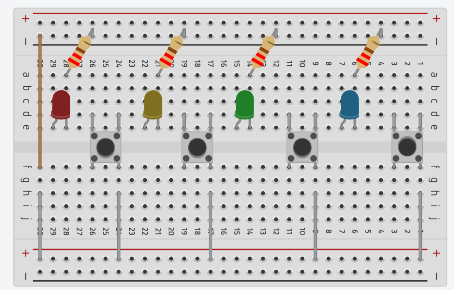
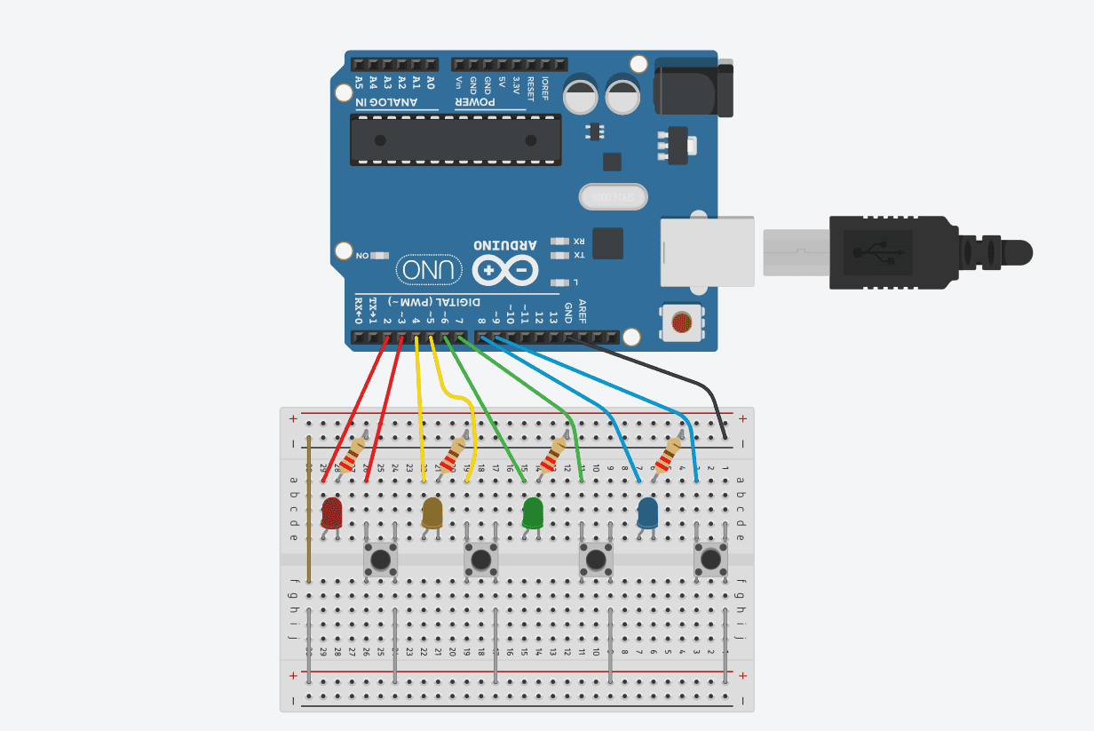
To ensure the hardware communicates correctly with the software, wire the components to the following digital pins on the Arduino:
LED Connections (Positive leg to Arduino):
-
Red LED: Pin 3
-
Yellow LED: Pin 5
-
Green LED: Pin 7
-
Blue LED: Pin 9
Button Connections (One side to Arduino):
-
Red Button: Pin 2
-
Yellow Button: Pin 4
-
Green Button: Pin 6
-
Blue Button: Pin 8
Step 1: Placing the Buttons
Plug your four buttons into the breadboard, spacing them three pins apart. Make sure they are placed across the center divider of the board. Connect one side of all four buttons to the ground (GND) rail. Connect the opposite side of each button to its designated Arduino pin using jumper wires. Ensure the ground rail used by the buttons is connected to the main ground rail shared with the LEDs.
Why do we do this?
The breadboard’s center gap physically separates the left and right electrical contacts of the board. Placing the buttons across this gap ensures the pins do not accidentally bridge until you actively press the button down.
Step 2: Preparing and Placing the LEDs
Using wire cutters, trim the long metal legs of the LEDs so they sit flush against the board. Insert them directly behind their matching buttons.
Why do we cut them unevenly?
LEDs are polar components, meaning electricity can only flow through them in one direction. The longer leg is positive (anode) and the shorter leg is negative (cathode). When trimming, ensure the positive leg remains slightly longer so you can accurately distinguish polarity during wiring.
Step 3: Wiring the Resistors
Use pliers to connect a 220-ohm resistor from the short (negative) leg of each LED over to the negative rail on the edge of the breadboard. Connect the positive leg of each LED to its designated Arduino pin.
Why do we need resistors?
The Arduino outputs 5 Volts of power, which exceeds the operating voltage of a standard LED. The resistor acts as a bottleneck to limit the current. Without it, the LED will draw too much power and immediately burn out.
Step 4: Connecting the Arduino and Common Ground
Route the colored jumper wires from your buttons and LEDs to the Arduino based on the pin layout provided above. Next, run one main wire from the breadboard’s negative rail straight to the GND pin on the Arduino.
Why do we do this?
Every electrical circuit requires a full, continuous loop to function; connecting the grounds completes that loop. Furthermore, the code utilizes a software-based “pull-down” setup. Grounding the buttons ensures that when a button is left unpressed, the Arduino reads a strict “Off” signal. Without this grounding, the pin acts like an antenna, and random static electricity in the room can trigger false button presses.
Step 5: Uploading the Code
The software code tells the Arduino which pins control the inputs and outputs, generates the random color sequence, and handles the logic for speeding up the game.
-
Copy the code below.
-
Open the file using the free Arduino IDE software.
-
Plug your Arduino Uno into your computer via a USB cable.
-
Select your board and COM port under the “Tools” menu, and click “Upload”.
// Pin Definitions
const int ledPins[] = {2, 4, 6, 8};     // Red, Yellow, Green, Blue
const int buttonPins[] = {3, 5, 7, 9};  // Red, Yellow, Green, Blue
const int numElements = 4;

// Game Variables
#define MAX_SEQUENCE 100
int sequence[MAX_SEQUENCE];
int currentLevel = 1;
const int playbackTotalTime = 5000; // Total time (5s) to show the whole sequence

void setup() {
  // Initialize pins
  for (int i = 0; i < numElements; i++) {
    pinMode(ledPins[i], OUTPUT);
    pinMode(buttonPins[i], INPUT_PULLUP); // Uses internal resistor, button reads LOW when pressed
  }

  // Seed the random number generator using an unconnected analog pin
  randomSeed(analogRead(A0));

  // --- 3-SECOND INITIAL PAUSE & COUNTDOWN ---
  // Give the user 3 seconds to prepare after upload/reset
  delay(3000);
}

void loop() {
  // 1. Generate the sequence up to the current level
  generateSequence();

  // 2. Play back the sequence to the user (compressed into exactly 5 seconds)
  playSequence();

  // 3. Get and check user input
  if (getUserInput()) {
    // SUCCESS: All LEDs flash for 3 seconds
    levelSuccess();
    currentLevel++;
    if(currentLevel >= MAX_SEQUENCE) currentLevel = 1; // Reset if they clear 100 rounds!
  } else {
    // FAILURE: Only Red LED flashes for 3 seconds
    levelFailure();
    currentLevel = 1; // Reset game back to level 1
  }

  delay(1000); // 1-second breather before the next sequence starts
}

// Fills the sequence array up to the current level with random choices (0 to 3)
void generateSequence() {
  for (int i = 0; i < currentLevel; i++) {
    sequence[i] = random(0, numElements);
  }
}

// Plays the sequence back, stretching or squeezing the flashes to perfectly fit 5 seconds
void playSequence() {
  int stepDuration = playbackTotalTime / currentLevel;
  int flashTime = stepDuration * 0.7; // LED is ON for 70% of the step
  int offTime = stepDuration * 0.3;   // LED is OFF for 30% of the step

  for (int i = 0; i < currentLevel; i++) {
    int currentLed = ledPins[sequence[i]];
    digitalWrite(currentLed, HIGH);
    delay(flashTime);
    digitalWrite(currentLed, LOW);
    delay(offTime);
  }
}

// Tracks player button presses and checks them against the sequence
bool getUserInput() {
  for (int i = 0; i < currentLevel; i++) {
    int expectedButton = sequence[i];
    int pressedButton = -1;

    // Loop and wait until a valid button press is detected
    while (pressedButton == -1) {
      for (int b = 0; b < numElements; b++) {
        if (digitalRead(buttonPins[b]) == LOW) { // LOW = button pressed
          pressedButton = b;
          digitalWrite(ledPins[b], HIGH); // Light up while player holds it
          while(digitalRead(buttonPins[b]) == LOW); // Wait for player to release button
          digitalWrite(ledPins[b], LOW);
          delay(50); // Debounce delay
          break;
        }
      }
    }

    // Immediately fail if the wrong button is pressed
    if (pressedButton != expectedButton) {
      return false;
    }
  }
  return true; // Passed the whole sequence
}

// Success Animation: All LEDs flash for 3 seconds
void levelSuccess() {
  unsigned long startTime = millis();
  while (millis() - startTime < 3000) {
    for (int i = 0; i < numElements; i++) digitalWrite(ledPins[i], HIGH);
    delay(250);
    for (int i = 0; i < numElements; i++) digitalWrite(ledPins[i], LOW);
    delay(250);
  }
}

// Failure Animation: Only the RED LED flashes for 3 seconds
void levelFailure() {
  unsigned long startTime = millis();
  int redLed = ledPins[0]; // Red is connected to Pin 2 (index 0)

  while (millis() - startTime < 3000) {
    digitalWrite(redLed, HIGH);
    delay(250);
    digitalWrite(redLed, LOW);
    delay(250);
  }
}
Step 6: Final Assembly
To convert the project into a portable console, unplug the USB cable and plug in your 9V battery using the DC adapter. Tape the battery to the back of the Arduino, and wrap the breadboard and Arduino tightly together using masking tape.
Why masking tape?
Masking tape is non-conductive, prevents the jumper wires from wiggling loose, and stabilizes the hardware. Ensure you do not tape over any exposed bare metal wires to prevent short circuits.
Troubleshooting Guide
If your game is not functioning properly, check the following:
-
LEDs are not lighting up: Verify the LED polarity. The longer leg (anode) must connect to the Arduino pin, and the shorter leg (cathode) must connect to the resistor and ground.
-
A specific button isn’t registering: Check that the jumper wire is securely seated in both the breadboard and the correct Arduino pin. Verify the opposite side of the button is correctly connected to the ground rail.
-
The game acts erratically or skips inputs: Check the common ground connection. If the breadboard’s ground rail is not wired to the Arduino’s GND pin, the circuit will float and behave unpredictably.
-
Code fails to upload: Double-check that the correct COM port and board model (Arduino Uno) are selected in the Arduino IDE.
Common Mistakes to Avoid
-
Omitting Resistors: Connecting LEDs directly to the Arduino’s 5V pins without a 220-ohm resistor will permanently damage the LEDs.
-
Incorrect Pin Assignments: Mixing up the LED and button pins. Ensure your wiring strictly follows the provided diagram (e.g., Red LED to Pin 3, Red Button to Pin 2).
-
Short Circuits: Allowing exposed wires or uninsulated component legs to touch one another on the breadboard. Keep wiring flush and separated.
-
Cutting LED Legs Equally: Trimming the LED legs to the exact same length makes identifying the positive and negative terminals difficult. Always leave the positive leg visibly longer.